1-8 Specifications TP-5631 7/96
Emergency
Stop
B+
B-
Emergency
Stop
Remote
Switch
AUX
OC
OS
LOP
HET
Common Fault **
** Common Fault Indicator
Activated By:
HET Fault
LOP Fault
LWT Fault
OC Fault
OS Fault
AUX Fault
Connect A/V Alarm or
Common Fault Relay Kit
LWT
Remove Jumper if
Emergency Stop is
Used.
System Ready
Not In Auto
PHET
PLOP
Low Fuel
Battery Charging Fault
Low Battery
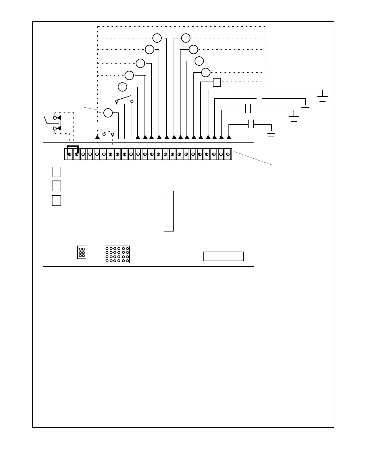
CIRCUIT BOARD TERMINAL IDENTIFICATION (TB1)
1 - Ground—Emergency Stop Relay (K4)—Connect Emergency Stop Across Terminals TB1-1 and 1A.
1A - Emergency Stop Relay (K4) Coil; Negative—Connect Emergency Stop Across Terminals TB1-1 and 1A.
56 - Not Used
- Not Used
42A - Battery Voltage (Fuse #1 Protected)—Accessory Power Supply; Customer may also Provide Separate Accessory Power Source
2 - Ground Terminal
9 - Crank Mode Selection (open—cyclic crank; ground—continuous crank) Connect TB1-2 to TB1-9 for Continuous
Cranking; Leave TB1-9 open for cyclic cranking. See Starting Procedure.
48 - Emergency Stop Indicator *
3 - Remote Start Ground—Connect Remote Start Switch to TB1-3 and TB1-4
4 - Remote Start—Connect Remote Start Switch to TB1-3 and TB1-4
26 - Auxiliary Indicator (Aux.) *
12 - Overcrank Indicator (OC) *
39 - Overspeed Indicator (OS) *
38 - Low Oil Pressure Indicator (LOP) *
36 - High Engine Temperature Indicator (HET) *
60 - System Ready Indicator *
80 - Not In Auto Indicator *
40 - Prealarm High Engine Temperature Indicator (PHET) *
41 - Prealarm Low Oil Pressure Indicator (PLOP) *
32 - Common Fault/Prealarm Line—A/V Alarm or Common Fault Relay Activated by HET, LOP, LWT, OC, OS, and AUX Faults
63 - Low Fuel—Connect Fuel Level Sensor to TB1-63 to Activate Fault Lamp (If Used)
61 - Battery Charger Fault—Connect Battery Charger to TB1-61 to Activate Fault Lamp (If Used)
62 - Low Battery Volts—Connect Battery Charger to TB1-62 to Activate Fault Lamp (If Used)
35 - Low Water Temperature—Connect LWT Sensor (Prealarm Kit) to TB1-35 to Activate LWT or LWT/AUX Lamp
NOTE: Not all terminal connections are used for all generator sets (see Wiring Diagrams).
* Indicators may be customer supplied lamps and/or alarms or A/V Alarms, Annunciators, Dry Contact Kits, etc.
TB1 Terminal Strip
1 42A 2 9 481A 56 3 4 26 12 39 38 36 60 80 40 41 32 63 61 62 35
P1
P2
.
Figure 1-9. Controller TB1 Terminal Strip Connections
 Loading...