6-2 Installation TP-5631 7/96
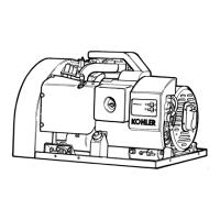
Exhaust Requirements
The exhaust muffler is located in a compartment in the
skid under the engine end of the generator set. See
Figure 6-2. The exhaust system is complete for
generator sets installed outdoors. The screened piece
coveringthemufflercompartmentpreventscontactwith
the hot exhaust system and keeps rodents and other
animals out.
For generator sets installed inside a building pipe
exhaust outside. Use available flexibleexhaust kit and
duct flange kit. Correctly size any extension added to
the exhaust outlet so it does not affect the maximum
allowablebackpressureof the engine. Totallengthand
number of bends in the exhaust system may have an
effect on the back pressure. Locate the exhaust outlet
to prevent entry by rodents and birds. Use a rain cap
when the exhaust outlet is directed upward.
ADV-5815C-A
Figure 6-2. Exhaust Muffler Location
Fuel System
Somegeneratorsetsmaybeequippedwithanemission
certified engine. Emission certified engines may be
fitted with carburetors that have no possible
adjustments.
Thegeneratorset canbefueledbygasoline, LP gas, or
natural gas. Gasoline requires a different fuel system
than the gas fuels. The gas fuels use the samesystem
butdifferentfuelregulators. Forinformationongasfuel
conversion, see Section 3, Gaseous Fuel Systems.
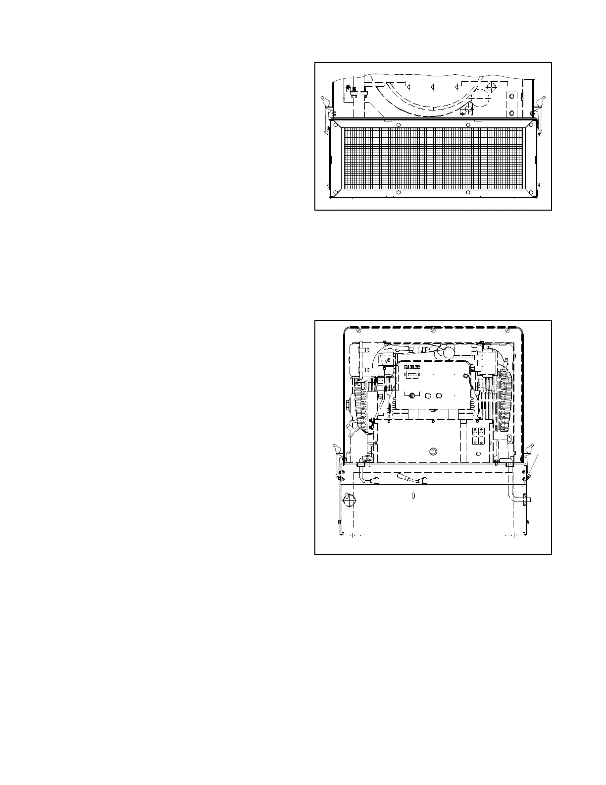
Thefuelinletconnectionforgasolinemodelsis arubber
hosewitha1/4in.(6mm)ID. Thegasfuelmodelshave
a fuel line with a 5/8-18 SAE 45° flare female swivel
connector. The rubber hose for all fuels is located near
thebatterycompartmentonthe6.5kW. Routethishose
as necessary to reach the fuel supply.
Complywithlocalandstatecodesregardingthecorrect
storage of fuel. Because of the scope of the topic
involving variable climate conditions and geographical
considerations, contact Authorized Service
Distributor/Dealer for fuel system planning and
installation. Protect all fuel lines from machinery or
equipment contact, adverse weather conditions, and
environmental damage.
10AMP
RUN
RESET/
OFF AUTO FAULT INPUT
1
ADV-5815B-A
1. Fuel inlet
Figure 6-3. Fuel Supply Line
(gas-fueled model shown)
 Loading...