AIR HANDLING UNIT FUTURE
INSTRUCTIONS FOR OPERATION AND MAINTENANCE
Filter secon FSTF
14 V. 2.0 2017-02-13
4.5. Maintenance
The filter section is to be serviced and cleaned twice a year, normally in the autumn and spring. The replace-
ment interval of the filters is usually determined by the maximum permissible decrease in the air flow due to
increased pressure drop across the filter (normally 10% of the design air flow).
To measure the pressure drop, a filter indicator indicating the pressure difference across the filter (shows the
pressure difference or gives an alarm) has been installed on the filter section. When the pressure difference
across the filter exceeds the set limit, the filter must be replaced. Refer to the unit design documentation for
the recommended filter-specific final pressure drop with design air flow.
The filter pressure difference values must under no circumstances exceed the dimensioning pressure drop in
the filter by more than two times. If the pressure difference is exceeded, the components or structure of the
unit may become damaged. The warranty does not cover damages due to negligence in replacing the filters.
Replace the filters if the pressure difference limit in the filters has been exceeded, or if the filters are dirty or
damaged.
• Check that the filters are intact and of the correct type.
• Check that the filters are tight against the frame gasket and that there are no leaks.
• Check that the filters are clamped in place.
• Check that the differential pressure gauge is intact and reset.
• Check that the differential pressure hoses of the filter section are intact and in their places.
• Check that the differential pressure transmitter operates properly and has been calibrated according
to the manufacturer’s instructions. Check also that a pressure difference limit, which must not exceed
the dimensioning pressure drop by more than two times, has been set in accordance with the Future
dimensioning program documentation.
4.6. Replacement of filters
1. Open the access door and the clamping mechanism. Pull the filter (filters) out of the casing.
2. Clean the casing, if necessary.
3. Check the condition of the gaskets. Replace worn and damaged gaskets. NOTE! Gaskets are not need-
ed between filters that are mounted parallel to each other.
4. Place new filters in the mounting grooves with the folds in upright position. Clamp the filters against
the gasket.
5. Close the access door.
6. Check the operation of the filter indicator once the fan has been restarted.
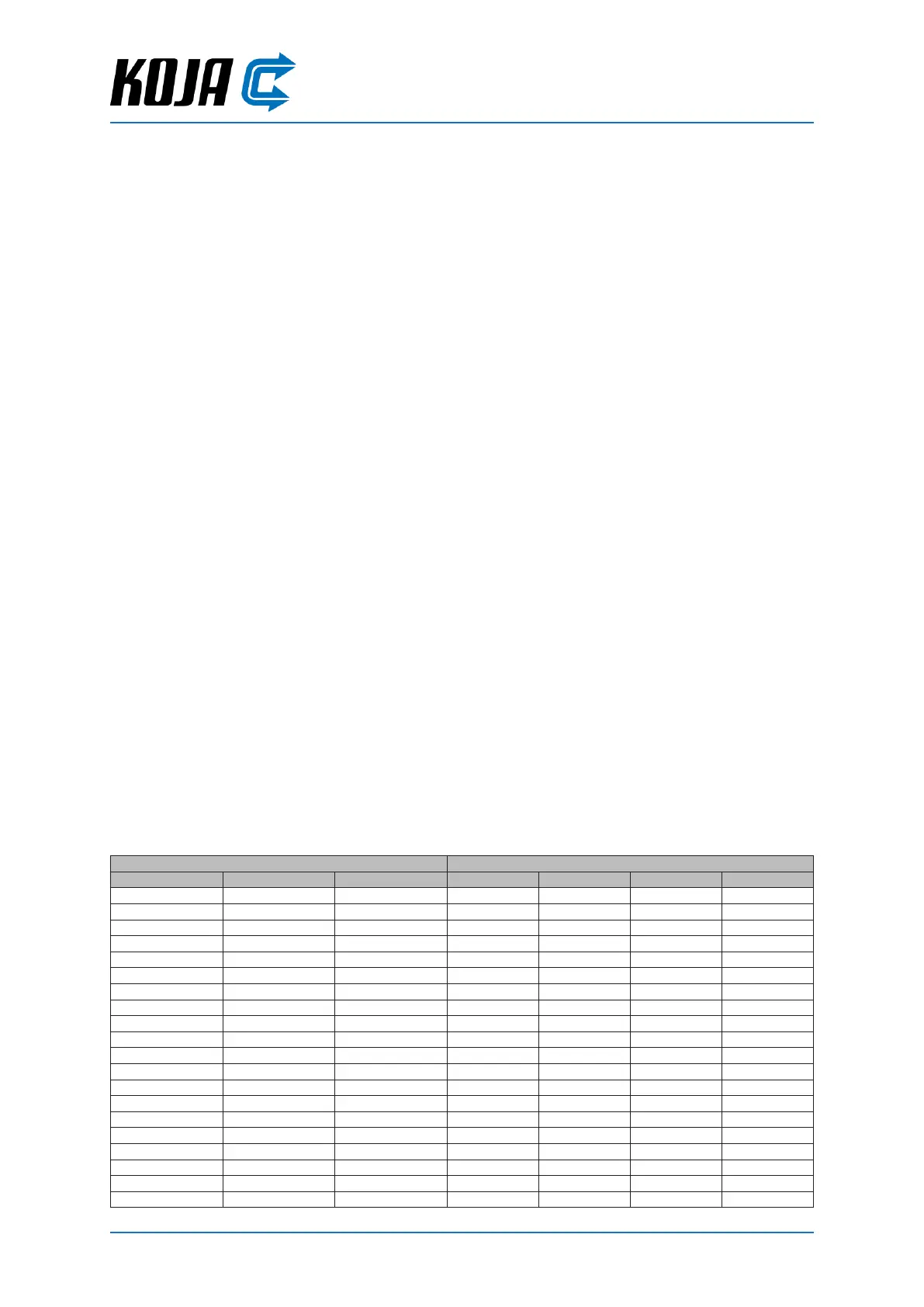
Filter cassee sizes / number of cassees
Unit size Width, mm Height, mm 287 x 592 592 x 287 592 x 592 592 x 490
0603 790 470 1
0605 790 670 1
0606 790 790 1
0906 1,070 790 1 1
0909 1,070 1,070 1 1 1
1206 1,350 790 2
1208 1,350 990 2 2
1209 1,350 1,070 2 2
1210 1,350 1,190 4
1212 1,350 1,350 4
1506 1,670 790 1 2
1509 1,670 1,070 1 2 2
1512 1,670 1,350 2 4
1515 1,670 1,670 2 2 4
1809 1,990 1,070 3 3
1810 1,990 1,190 6
1812 1,990 1,350 6
1815 1,990 1,670 3 6
1818 1,990 1,990 9
2409 2,550 1,070 4 4