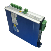
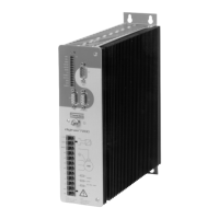
I.5.2 Digital servo amplifier concept
Operation and parameter setting
Via the parallel interface of a PC using the special operator software BS7200
Power section
Mains supply : B6 bridge rectifier with current inrush limiter, directly off
the 3-phase 400V mains
Output stage : IGBT-module with electrically isolated current measurement
Ballast circuit : With electronic monitoring and internal ballast resistor.
Digital functions
— Current and speed control
— Processing of the 14-bit resolver evaluation
— Position output (incremental or SSI) with analog setpoint input
— Communication with the various interface modules and positional control,
if an interface module is installed
Easy-to-use functions
adjustable setpoint ramps, limit-switch function, analog monitor outputs
I.5.3 Operation directly off a 400V mains
Power supply — Directly off a 3-phase 400V mains without transformer,
mains filter series 3EFxx
— Fuse protection and phase-failure monitoring by the user
— Single-phase supply (only for power < 0.5kW) e.g. as a possibility
during commissioning or setting-up
Aux. supply — Electrically isolated, from an external 24V DC- power supply
25V DC with isolating transformer, mains filter 1EF06
— For a short time, at the instant of switching on, the power supply has to
provide twice the rated current, so that the power sections can start up the
servo amplifiers which are connected.
Intrinsic safety — Electrically safe isolation to VDE 0160 (proposed EN 50178)
between the mains or motor connection and the signal electronics
through appropriate creepage distances and full electrical isolation.
— Soft start, overvoltage detection, short-circuit protection
— Temperature monitoring of the servo amplifier and motor
(when using motors from the 6SM series with our preassembled cables)
Additional interference suppression measures
— Mains filter (see chapter V.1)
— Motor choke (see chapter I.11)
Please consult us in the event of difficulty with an application.
PageI-4 General Chapter I
03.98 digifas
®
7200 series
 Loading...