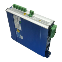
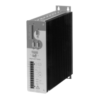
III Control inputs and outputs
III.1 Input functions
III.1.1 Analog inputs
Setpoint input SW
The servo amplifier is equipped with a decoupled differential input for an analog setpoint.
It is set for a differential input voltage of max. ± 10 V, resolution 1mV.
Ground reference: AGND, terminal X3/17.
A positive voltage on terminal X3/1 with regard to terminal X3/2 produces a clockwise rotation of
the motor shaft (looking at the shaft). The common-mode voltage range (important to avoid
earth loops) amounts to an additional ± 10 V, input resistance: 20 kW.
III.1.2 Digital control inputs
All inputs are isolated and coupled via optocouplers. The ground reference is Digital-GND
(DGND, terminal X3/12). The logic is designed for +24V/7mA (PLC compatible),
logic-high level is +12 ... 30V / 7mA.
Enable input E
The output stage of the amplifier is enabled by the Enable signal (terminal X3/16, input 24V,
active high). The attached motor is torque-free in the disabled state.
P
STOP / NSTOP (limit switch) inputs
Limit switch positive/negative (PSTOP / NSTOP, terminals X3/10 and 11), high level in normal
operation (fail-safe for cable break). A low signal (open) disables the corresponding direction of
rotation, the ramp function remains active. If the inputs are blocked the I-component of the
speed controller will also become ineffective, so that a mechanical demarcation (dead stop) is
permissible. This function must be explicitly enabled (parameter LIMIT SWITCH to ON).
If the parameter LIMIT SWITCH is set to STOP, the result is a controlled drift-free standstill of
the motor, with the standstill torque M
0
, when the limit switch inputs are disabled (I-component
is active).
Programmable input
I/0
Terminal X3/15 (I/O) can be programmed by means of the I/O parameter for the following input
functions (see Chapter II.2.2 for a wiring example) :
— RESET : hardware reset of the servo amplifier (active high)
— 1:1 CONTROL : servo amplifier operates purely as a current controller (active high)
— INT. OFF : switches offf the I-component of the speed controller (active high)
Ground reference : DGND (terminal X3/12)
Chapter III Control inputs and outputs Page III - 1
digifas
®
7200 series 03.98
Warning !
Do not program terminal X3/15 as an output if it is wired up as an input !
 Loading...