Contents Page - A -
digifas
®
7200 series 03.98
I General
I.1 About this manual ..............................................................I-1
I.2 Prescribed usage of the servo amplifiers ............................................I-1
I.3 Abbreviations used in this manual..................................................I-2
I.4 Nameplate....................................................................I-2
- A.4.028.6/10
I.5 Equipment description...........................................................I-3
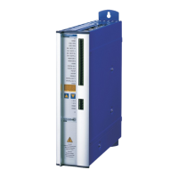
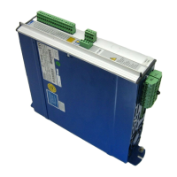
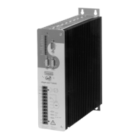
I.5.1 The digifas™ 7200 series of digital servo amplifiers .................................I-3
I.5.2 Digital servo amplifier concept ..................................................I-4
I.5.3 Operation directly off a 400V mains ..............................................I-4
I.6 Block diagram .................................................................I-5
- A.4.011.4/14
I.7 Frontal view: digifas™ 7200 operating components and connections ......................I-6
- A.4.011.4/9
I.8 Technical data of the digifas™ 7200 series ..........................................I-7
I.8.1 Permissible ambient conditions, ventilation, mounting position .........................I-8
I.8.2 Lead cross-sections ..........................................................I-8
I.8.3 Fuse protection .............................................................I-8
I.8.4 LED display ................................................................I-9
I.9 System grounds ...............................................................I-9
I.10 Ballast circuit ..................................................................I-9
I.11 Motor choke box 3YL-06 ........................................................I-10
- A.4.018.4/1
II Installation and commissioning
II.1 Important instructions...........................................................II-1
II.2 Installation ...................................................................II-2
II.2.1 - correct wiring , general diagram.............................................II-4
- A.4.011.1/4
II.2.2 Pin assignments for standard unit...............................................II-5
- A.4.011.4/15
II.2.3 Wiring diagram standard unit for motor series 6SM27/37/47/57/77 .....................II-6
- A.4.011.1/14
II.2.4 Wiring diagram standard unit for motor series 6SM45,56.............................II-7
- A.4.011.1/6
II.2.5 Wiring example: multi-axis system ..............................................II-8
- A.4.011.1/10
II.2.6 Notes on connection methods..................................................II-9
II.2.6.1 Using the shield connection terminal clamps .................................II-9
- A.4.029.4/1
II.2.6.2 Connecting the SubD9 connector ........................................II-10
- A.4.029.4/2
II.2.6.3 Using shielded leads with terminals .......................................II-11
- A.4.029.4/3
II.2.6.4 Using motor cable without brake (amplifier side) .............................II-12
- A.4.029.4/4
II.2.6.5 Using motor cable with brake (amplifier side) ................................II-13
- A.4.029.4/5
II.3 Commissioning...............................................................II-14
II.4 Parameter description .........................................................II-16
II.4.1 General ..................................................................II-16
II.4.2 Current controller ..........................................................II-17
II.4.3 Speed controller ...........................................................II-17
II.4.4 Service functions...........................................................II-18
II.4.5 Display actual value ........................................................II-18
II.5 Fault signals, BTB signal .......................................................II-18
Contents Diagram Page
Contents ...............................................A
Safety instructions ........................................C
Directives and standards ....................................D
- conformance .........................................D
 Loading...