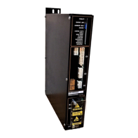
DS4 C
HAPTER
2 - I
NSTALLATION
2-3
2.5.1 Environmental Considerations
The environment that this equipment is placed in can
have dramatic effects on its operation. Industrial
Drives recommends that the BDS4 and PSR4/5 be
operated and stored under the following conditions:
•
Operating Temperature: 0
°
C to 45
°
C
•
Storage Temperature: -20
°
C to 70
°
C
•
Humidity: 10% to 90% (Non Condensing)
2.5.2 Enclosures
It is suggested that the BDS4 and PSR4/5 be mounted
in a cabinet or other suitable enclosure to protect
them from physical and environmental damage.
Refer to Appendix D for complete system
dimensions.
CAUTION
Allow sufficient clearance for
the large "regenerative" heat
producing resistor(s)
mounted at the upper edge
of the PSR4/5 unit and the
externally mounted regen
(shunt regulator) power
resistor(s).
2.6 ASSEMBLY
The BDS4 and PSR4/5 are both constructed prior to
shipping from the factory. The only assembly
required is the mounting of the devices.
2.6.1 Mounting
Refer to the drawing of your model system in
Appendix F for outline and dimensions. Be sure to
look at the proper drawing for mounting
measurements.
The PSR4/5 and BDS4 modules should be mounted
in the vertical position. To minimize cross talk and
enhance air flow, maintain a minimum of 20
millimeters (0.75 in.) on either side of each unit and
at least 40 millimeters (1.5 in.) of unobstructed space
above and below the units.
Depending on the continuous current ratings of the
BDS4 and PSR4/5 modules, a total of six (6)
amplifiers may be mounted with a single power
supply. However, the maximum number of BDS4
amplifiers mounted on either side of the PSR4/5
power supply module must not exceed four (4).
Mounting combinations for the PSR4/5 and BDS4
modules are as follows:
•
PSR4/5-X12; a maximum of four (4) BDS4
amplifiers sequentially or "split mounted"
(amplifiers are mounted on both sides of the
PSR4/5) at either side of the PSR4/5 in
descending order of continuous current ratings.
•
PSR4/5-X20; a maximum of four (4) BDS4
amplifiers sequentially or "split mounted" at
either side of the PSR4/5 in descending order of
continuous current ratings.
•
PSR4/5-X50; a maximum of six (6) BDS4
amplifiers ("split mounted" only) to either side,
not to exceed four (4) amplifiers on a side,
mounted in descending order of continuous
current ratings.
•
PSR4/5-X75; a maximum of six (6) BDS4
amplifiers ("split mounted" only) to either side,
not to exceed four (4) amplifiers on a side,
mounted in descending order of continuous
current ratings.
NOTE
Refer to The drawing of your
model system in Appendix F
for the Mounting Hole Pattern
information.
CAUTION
Allow sufficient clearance for
the large "regenerative" heat
producing resistor(s). The
internal resistors are
mounted at the upper edge of
the PSR4/5 unit. The
externally mounted regen
(shunt regulator) power
resistor(s) are mounted
above the PRS4/5A unit.
Artisan Technology Group - Quality Instrumentation ... Guaranteed | (888) 88-SOURCE | www.artisantg.com

 Loading...