HAPTER
2 - I
NSTALLATION
BDS4
2-10
2.7.9 Connecting the Motor
NOTE
B SERIES MOTORS
have a
thermostat switch wired to the
resolver connector at the
motor.
BR SERIES MOTORS
have a
thermostat switch wired to the
stator connector at the motor.
CAUTION
The motor thermostat switch
is an automatic resetting
device and should be
connected directly into a
latched (locked out) power
down type circuit.
WARNING
Incorrect motor resolver
phasing can cause erratic
operation, runaway, or
damage to the system.
Terminate Pins A, B, C, D, E, and F of the resolver
connector at Connector C2 on the BDS4 as shown by
Figures 2.5 and 2.6. Also see the BDS4 Wiring
Diagram (A-93231) and the appropriate motor HD
(hook-up) drawing or Motor Connection Diagram (A-
63542). Use cables with three (3) independently
shielded pairs for the resolver.
The leads of the three-phase synchronous motor are
brought out to Pins A, B, and C of the motor
connector. Pin D is ground for the motor. Refer to
Figure 2.7 for pin connections.
Terminate Pins A, B, and C of the motor connector to
Ma, Mb, and Mc, respectively, on the power terminal
block located on the front of the BDS4 amplifier.
Terminate Pin D at the BDS4 chassis ground screw.
Refer to Wiring Diagram (A-93231) and the
appropriate motor HD (hook-up) drawing.
The optional integrally-mounted tachometer is
brought out to Pins R and S on the resolver connector
for both the B and BR series motors. Pin R (Tach Hi)
should be terminated at Connector C1 - Pin 12 (Aux
In) of the BDS4. Pin S (Tach Lo) should be
terminated at Connector C1 - Pin 15 (common) of the
BDS4. The tachometer is an option and is not
installed on most motors.
2.8 INSTALLATION CHECKLIST
Refer to BDS4 Wiring Diagram (A-93231).
Before applying power to the PSR4/5 and BDS4,
check the following items to ensure proper operation:
CAUTION
To prevent damage to the
equipment, the motor and
resolver, the AC line voltage,
and the DC bus voltages must
be connected as indicated by
BDS4 Wiring Diagram (A-
93231).
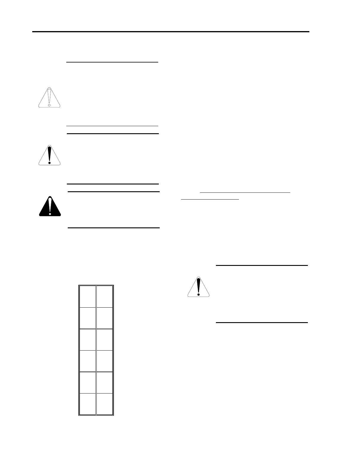
SIN HI 7 1 SIN LO
SIN SHIELD 8 2 COS SHIELD
COD HI 9 3 COS LO
REF LO 10 4 REF HI
SPARE SHIELD 11 5 REF SHIELD
N/C 12 6 N/C
Figure 2.5. BDS4 (C2)
Artisan Technology Group - Quality Instrumentation ... Guaranteed | (888) 88-SOURCE | www.artisantg.com
 Loading...


