DS4 C
HAPTER
2 - I
NSTALLATION
2-11
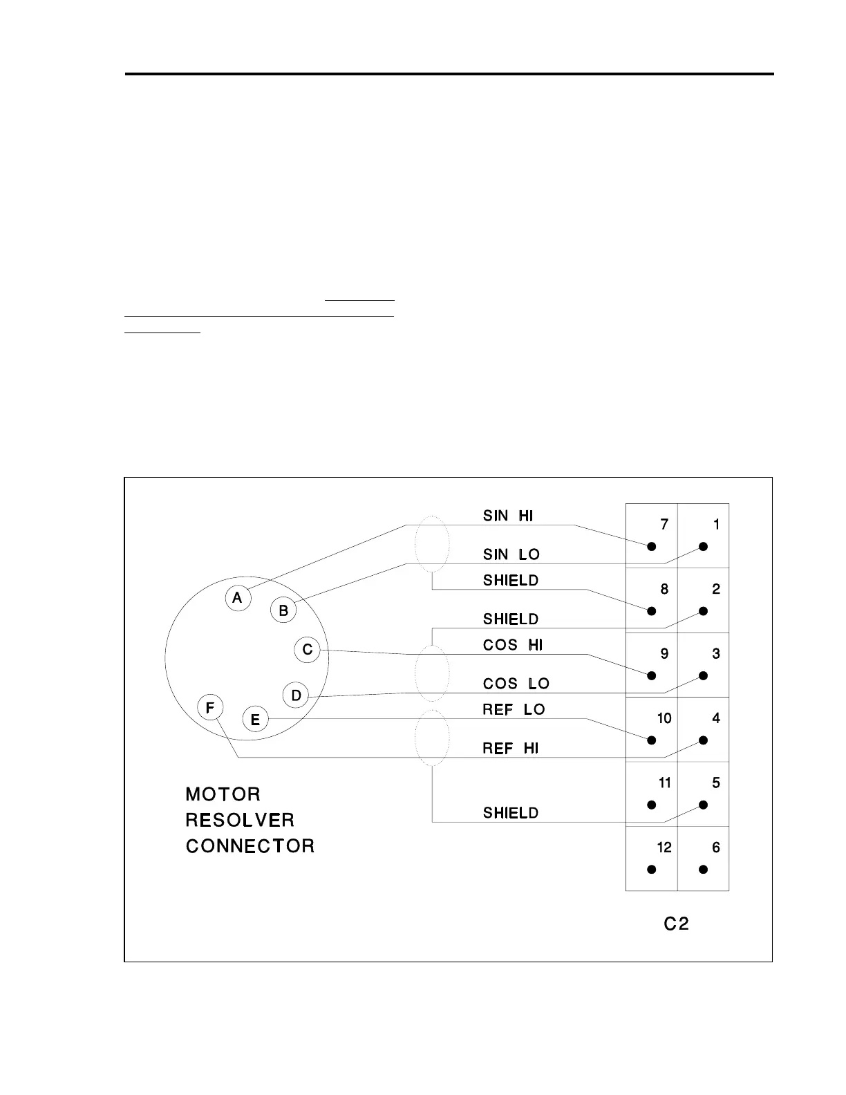
2.8.1 Checking the Motor and
Resolver Wiring
Disconnect both the motor stator and resolver
connectors from the motor. Using an ohmmeter,
check the continuity of each motor stator lead
between the motor stator connector pin and the
BDS4. Using an ohmmeter, check the continuity of
each motor resolver lead between the motor resolver
connector pin and the BDS4. The motor stator and
resolver leads should be connected according to
BDS4 Wiring Diagram (A-93231). There are no
other options for connecting the motor stator and
resolver leads.
2.8.2 Checking the AC Line Voltages
Open the circuit breaker or remove the fuses in the
Main AC lines that are connected to the PSR4/5 at L
a
,
L
b
, and L
c
. Remove Connector C1 from the PSR4/5,
and remove (if present) Connector C4 from the
BDS4.
Apply only the AC main power. Use an AC
voltmeter to check and record the 1- or 3-phase line-
to-line voltage at the circuit breaker or fuse holders.
Remove power. Note the model number of the
PSR4/5 and refer to Appendix B to confirm the
correct Main AC voltage level.
Figure 2.6. Motor Resolver Connections
Artisan Technology Group - Quality Instrumentation ... Guaranteed | (888) 88-SOURCE | www.artisantg.com
 Loading...


