HAPTER
2 - I
NSTALLATION
BDS4
2-12
Apply only the AC control power. Use an AC
voltmeter to check and record the single-phase
voltage at Connector C1 of the PSR4/5. Remove
power. Note the model number of the PSR4/5 and
refer to Appendix B to confirm correct Control AC
voltage level.
If the voltage levels are within the specifications
listed in Appendix B, proceed with the Check-Out
procedure.
Close the circuit breaker or re-install the fuses for the
Main AC input power. Re-install Connectors C1 and
C4 (if present).
2.8.3 Checking the DC Bus Voltages
WARNING
Allow sufficient time (after
removing power from the
system) for the voltage to
bleed down before connecting
or disconnecting wires at the
bus.
Remove power.
Remove the Bus+ and Bus- leads from the PSR4/5
power terminal block. Remove mating Connector C2
from the PSR4/5.
Apply power.
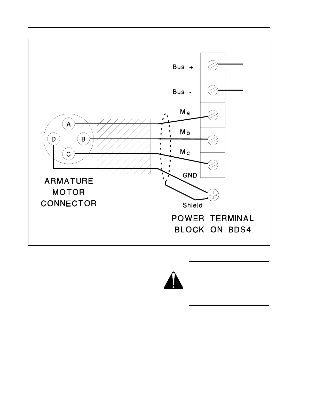
Figure 2.7. Armature Motor Connections
Artisan Technology Group - Quality Instrumentation ... Guaranteed | (888) 88-SOURCE | www.artisantg.com
 Loading...


