SEN04130-01 50 Disassembly and assembly
2 PC130-8
Removal and installation of center
swivel joint assembly 1
Removal
k Stop the machine on a level ground, lower
the work equipment to the ground, stop the
engine, and set the lock lever in the lock
position.
k Disconnect the cable from the negative (–)
terminal of the battery.
k Loosen the hydraulic tank cap gradually to
release the pressure in the hydraulic tank.
a Put t
ags to the pipings to prevent a mistake in
re-connecting them.
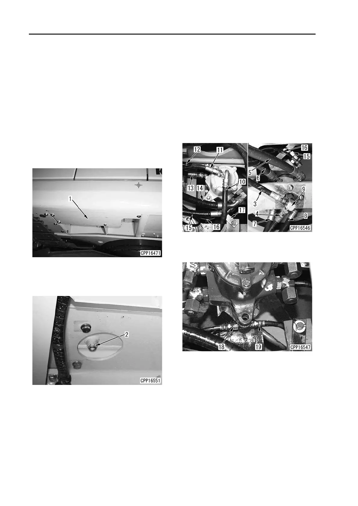
1. Remove undercover (1).
2. Loosen hydraulic oil drain plug (2) and drain
the hydraulic oil. [*1]
6 Hydraulic tank: 90 l
(Specified quantity of oil): 14
5 l
3. Disconnect hoses (3) – (8) between travel
motor and swivel joint.
4. Remove elbow (9).
5. Disconnect drain hose (10), (11).
6. Disconnect hoses (12) – (15) between control
valve and swivel joint.
7. Disconnect hose (16) from solenoid valve.
8. Remove plate (17).
9. Disconnect hoses (for changing the speed)
(18) and (19) between both travel motors and
swivel joint.