Do you have a question about the Komatsu Galeo PC138US-8 and is the answer not in the manual?
Explains the structure, sections, and symbols used in the shop manual for understanding.
Crucial safety precautions and general guidelines for operating and maintaining the machine.
Defines terms like standard size, tolerance, clearance, interference, and repair limits.
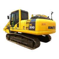
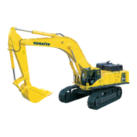
Provides detailed dimensions and specifications of the machine's components and overall structure.
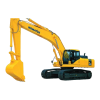
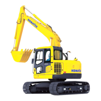
Illustrates the operational reach and depth capabilities of the excavator's work equipment.
Lists recommended fluids and lubricants for various machine components and operating temperatures.
Details the structure, function, and maintenance standards for the engine and cooling system components.
Explains the structure, function, and maintenance standards for the power train components like idlers and drive motors.
Covers the layout, control valve, and hydraulic pump, detailing their structure and function.
Details the electronic control system, monitor system, KOMTRAX, and sensors, including input/output signals.
Provides standard values and judgment criteria for testing, adjusting, and troubleshooting machine parts.
Covers procedures for testing and adjusting engine components, fuel system, and basic hydraulic circuits.
Details special functions of the machine monitor, switches, and control methods for various systems.
Focuses on troubleshooting electrical system errors, including voltage issues and sensor failures.
Lists failure codes, their descriptions, alarm indicators, component in charge, and reference documents.
Provides general guidelines, troubleshooting procedures, and checks to perform before starting.
Details troubleshooting steps for engine-related failure codes from 989L00 to CA332.
Guides on diagnosing electrical system issues when the machine monitor displays error codes.
Explains how to read the manual, lists adhesives, special tools, and removal/installation procedures.
Covers removal and installation procedures for various engine and cooling system components.
Details removal and installation procedures for travel motors, final drives, swing motors, and swing circles.
Provides procedures for disassembling and assembling track rollers, idlers, recoil springs, track shoes, sprockets, and frames.
Covers removal and installation of components like center swivel joints, hydraulic tanks, pumps, and control valves.
Details removal and installation procedures for work equipment assemblies such as boom, arm, and bucket.
Covers removal and installation of operator cab assembly, glass, front window, and floor frame.
Provides removal and installation procedures for air compressor, air conditioner, machine monitor, pump controller, engine controller, and KOMTRAX module.
Illustrates the hydraulic system with detailed diagrams of circuits and component connections.
Presents the electrical circuit diagrams and connector tables for troubleshooting and maintenance.
| Brand | Komatsu |
|---|---|
| Model | Galeo PC138US-8 |
| Category | Excavators |
| Language | English |