SEN03856-00
WA250, 250PZ-6 50-500 57
500 Hydraulic system
Disassembly and assembly of hydraulic cylinder assembly
Disassembly and assembly of
hydraulic cylinder assembly
1
Special tools
Disassembly
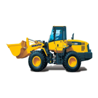
1. Cylinder assembly
Set cylinder assembly (1) to tool U1.
2. Cylinder head and piston rod assembly
(Steering cylinder and lift cylinder)
1) Using tool U2, remove cylinder head (2)
from the cylinder.
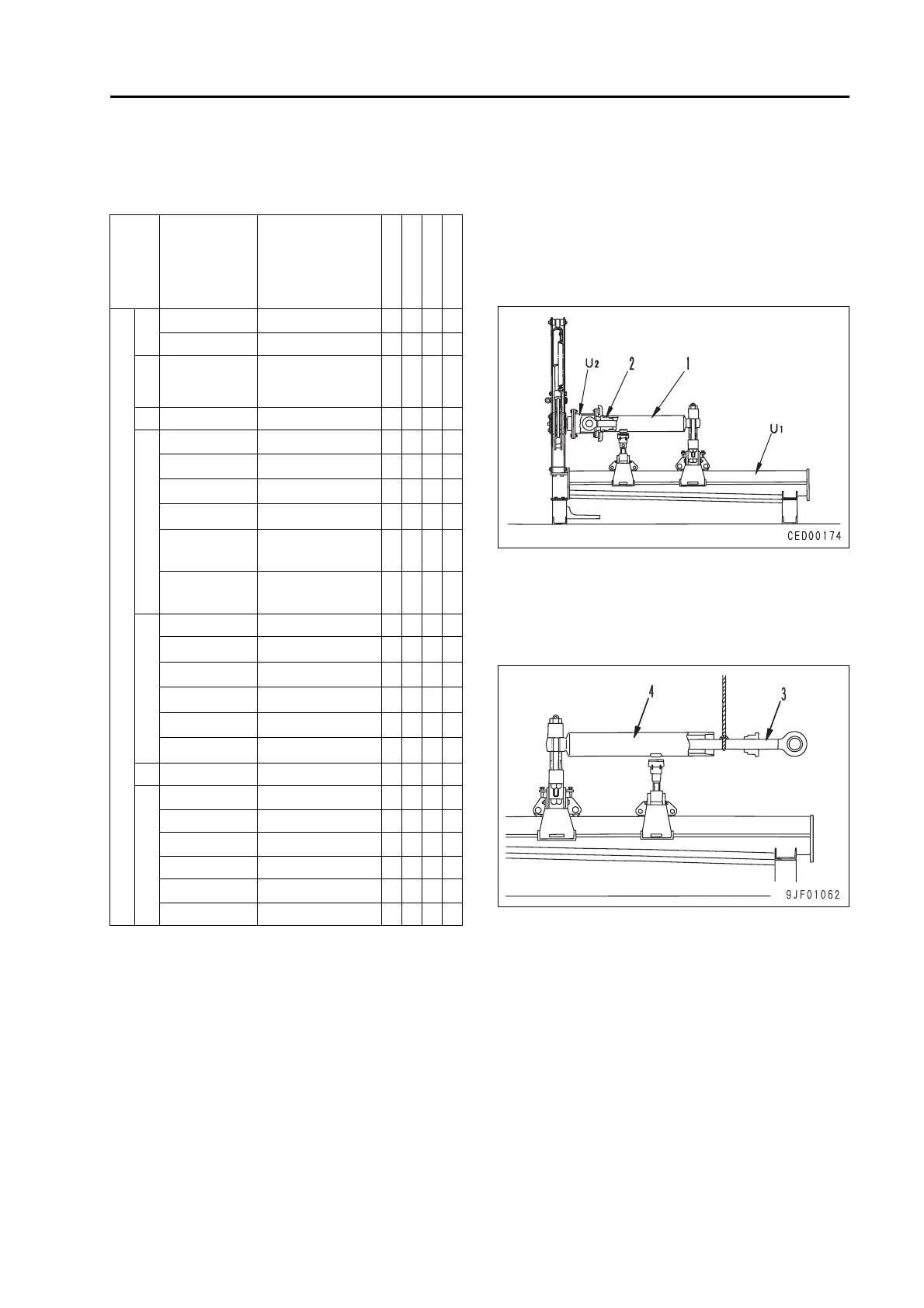
2) Pull cylinder head and piston rod assem-
bly (3) out of cylinder (4).
a Since oil will flow out when the piston
rod assembly is pulled out of the cyl-
inder, prepare an oil receiver.
Symbol Part No. Part Name
Necessity
Q'ty
New/Remodel
Sketch
U
1
790-502-1003 Repair stand t 1
790-101-1102 Hydraulic pump t 1
2
790-102-2303
or
790-102-3802
Wrench assembly
(for lift and bucket)
t 1
3 790-302-1340 Socket (for lift) t 1
4
790-201-1702 Push tool kit t 1
790-101-5021
•Grip
1
01010-50816
•Bolt
1
790-201-1811
• Push tool (Lift)
1
790-201-1821
• Push tool
(Bucket)
1
790-201-1741
• Push tool
(Steering)
1
5
790-201-1500 Push tool kit t 1
790-101-5021
•Grip
1
01010-50816
•Bolt
1
790-201-1620
• Plate (Lift)
1
790-201-1630
• Plate (Bucket)
1
790-201-1550
• Plate (Steering)
1
6 790-720-1000 Expander Q 1
7
796-720-1670 Ring (Lift) Q 1
07281-01279 Clamp (Lift) Q 1
796-720-1680 Ring (Bucket) Q 1
07281-01589 Clamp (Bucket) Q 1
796-720-1740 Ring (Steering) Q 1
07281-00809 Clamp (Steering) Q 1
CED00174
9JF01062
 Loading...