SEN03836-01
30-110
16
WA250, 250PZ-6
110 Testing and adjusting, Part 1
Measuring compression pressure
Measuring compression pressure
1
a Necessary tools
k
When measuring the compression pres-
sure, take care not to burn yourself on the
exhaust manifold or muffler or get caught
in a rotating part.
a Measure the compression pressure after the
engine is warmed up.
(Engine oil temperature: 40 – 60°C)
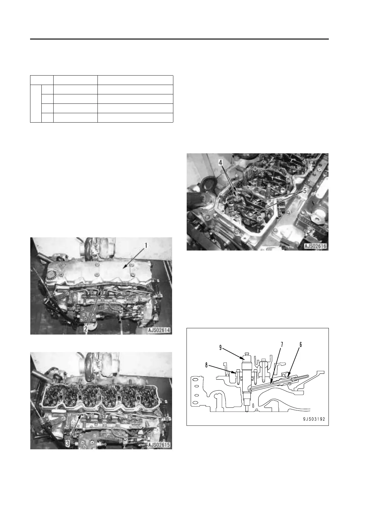
1. Remove cylinder head cover (1). For details,
see Disassembly and assembly, “Removal and
installation of cylinder head assembly”.
2. Disconnect 3 injector wiring harness connec-
tors (2) and move the wiring harnesses.
3. Disconnect fuel high-pressure tube (3).
4. Loosen injector terminal nut (4) and remove
the terminal from the injector.
5. Set the cylinder to be checked to the compres-
sion top dead center.
a How to turn the crankshaft, refer to
“Adjusting valve clearance”.
a When the cylinder is at the compression
top dead center, the rocker arm of the cyl-
inder can be moved by the valve clear-
ance with the hand.
6. Remove rocker arm assembly (5).
7. Remove retainer (6) and fuel inlet connector (7).
8. Remove holder (8).
9. Remove injector (9).
a Using puller C1, remove the injector with
impacts of a slide hammer.
a Do not remove the injector by prying its
top up.
Symbol Part No. Part Name
C
1 795-799-6700 Puller
2 795-502-1590 Gauge assembly
3 795-790-4410 Adapter
4 6754-11-3130 Gasket
 Loading...