SEN03837-01
30-120 26 WA250, 250PZ-6
120 Testing and adjusting, Part 2
Bleeding air from wheel brake circuit
Bleeding air from wheel brake
circuit
1
Necessary tools
k Stop the machine on a level ground, lower
the work equipment to the ground, and set
chocks under the tire securely.
a If a brake circuit part is removed and installed,
bleed air from the brake circuit according to the
following procedure.
a Bleed air from the front brake circuit and rear
brake circuit similarly (2 places each).
a When a complete bleeding is required, it is
advisable to start the operation from the brake
cylinder situated farthest from the brake pedal.
a The work on the front right side is shown as an
example. Work on each brake cylinder simi-
larly.
1. Start the engine to accumulate pressure in the
accumulator and then stop the engine.
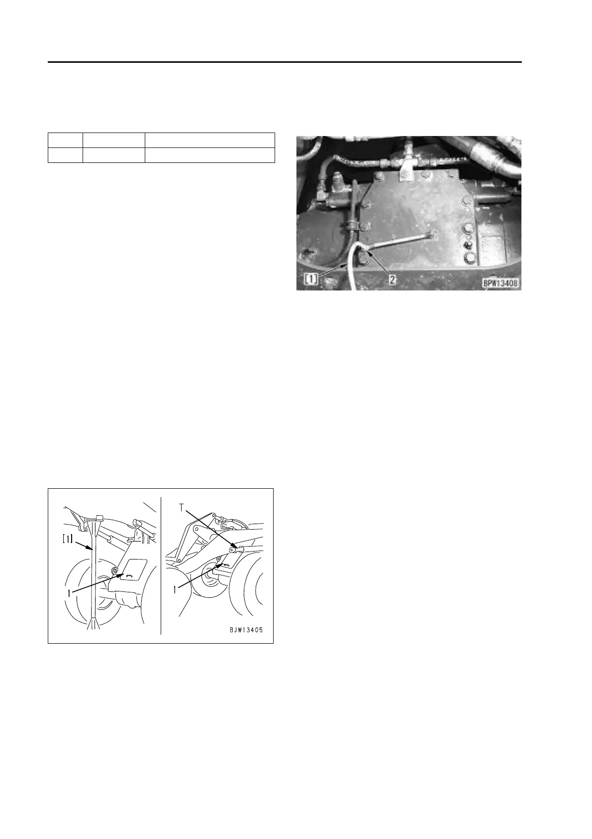
2. Remove front frame inspection cover (1).
k When raising the lift arm and removing
the inspection cover, place support
stand [1] under the lift arm to support
the lift arm securely or set stopper T to
the lift arm cylinder to prevent the work
equipment from falling.
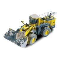
3. Connect hose [1] to bleeder screw (2) and
place hose [1] in the oil receive pan.
a Work on the rear side similarly from under-
side of the machine.
4. Press the brake pedal and then loosen bleeder
screw (2) to bleed air.
a Return the brake pedal slowly after tight-
ening bleeder screw (2).
5. Repeat this operation until the oil flowing
through hose [1] becomes free from bubbles.
Then press the pedal fully and tighten bleeder
screw (2) while the oil is flowing.
a As accumulated pressure in the accumu-
lator is decreased, start the engine to
accumulate pressure in the accumulator.
Then bleed air using the same procedure
as described above.
a After finishing bleeding air, run the engine
at low idle and check the oil level in the
hydraulic tank. If the level is low, add oil up
to the specified level.
6. After finishing the work, remove the measuring
instruments and return the removed parts.
Symbol Part No. Part name
T 793-403-1100 Stopper

 Loading...