SEN03843-00
40-330 8 WA250, 250PZ-6
330 Troubleshooting by failure code (Display of code), Part 3
Failure code [CA431] Idle validation switch error
Failure code [CA431] Idle validation switch error 1
Action code Failure code
Trouble
Idle validation switch error
(Engine controller system)
E01 CA431
Contents of
trouble
• Abnormality occurred in idle validation switch circuit
Action of
controller
• Operates at position of throttle of throttle sensor.
Problem that
appears on
machine
—
Related
information
• The input state (ON/OFF) from the idle validation switch 1 can be checked with the monitoring func-
tion (Code: ENGINE, 18300, IVS 1).
• The input state (ON/OFF) from the idle validation switch 2 can be checked with the monitoring func-
tion (Code: ENGINE, 18301, IVS 2).
• Method of reproducing failure code: Turn the starting switch ON.
Possible causes
and standard
value in normal
state
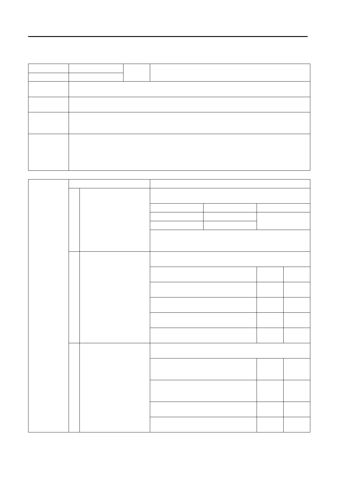
Causes Standard value in normal state/Remarks on troubleshooting
1
Defective accelerator pedal
(Internal trouble)
a Prepare with starting switch OFF, then turn starting switch ON
and carry out troubleshooting.
PD1 Signal name Voltage
Between (5) and (4) Signal 1
See Fig. 1
Between (6) and (4) Signal 2
Sensor voltage is measured with wiring harness connected. Accord-
ingly, if voltage is abnormal, check wiring harness and controller for
another cause of trouble before judgment
2
Disconnection in wiring har-
ness
(Disconnection or defective
contact in connector)
a Prepare with starting switch OFF, then carry out troubleshooting
without turning starting switch ON.
Wiring harness between EC2 (female) (11) –
PD1 (female) (5)
Resis-
tance
Max. 1 z
Wiring harness between EC2 (female) (1) –
PD1 (female) (6)
Resis-
tance
Max. 1 z
Wiring harness between EC2 (female) (32) –
PD1 (female) (4)
Resis-
tance
Max. 1 z
Wiring harness between EC2 (female) (21) –
PD2 (female) (1)
Resis-
tance
Max. 1 z
Wiring harness between EC2 (female) (29) –
PD2 (female) (2)
Resis-
tance
Max. 1 z
3
Short circuit in wiring har-
ness
(with another wiring harness)
a Prepare with starting switch OFF, then carry out troubleshooting
without turning starting switch ON.
Wiring harness among all pins between EC2
(female) (11) – EC2 (female) (PD1 and 2,
too, is disconnected.)
Resis-
tance
Min.
100 kz
Wiring harness among all pins between EC2
(female) (1) – EC2 (female) (PD1 and 2, too,
is disconnected.)
Resis-
tance
Min.
100 kz
Between EC2 (female) (11) – EC3 (female)
(3), (4) (PD1 and 2, too, is disconnected.)
Resis-
tance
Min.
100 kz
Between EC2 (female) (1) – EC3 (female)
(3), (4) (PD1 and 2, too, is disconnected.)
Resis-
tance
Min.
100 kz

 Loading...