EN
UAB KOMFOVENT we reserve the right to make changes without prior notice
C5.1-20-05
6
Air humidier operation
Summer night cooling
mode
Weekly operation mode
Holiday operation mode
„Override“ mode
Alarm signal
Fan operation
Air ow increasing
by activated function
(see chapter Functions)
Air ow decreasing
by activated function
(see chapter Functions)
Energy recovery
operation
Air heater operation
Air cooler operation
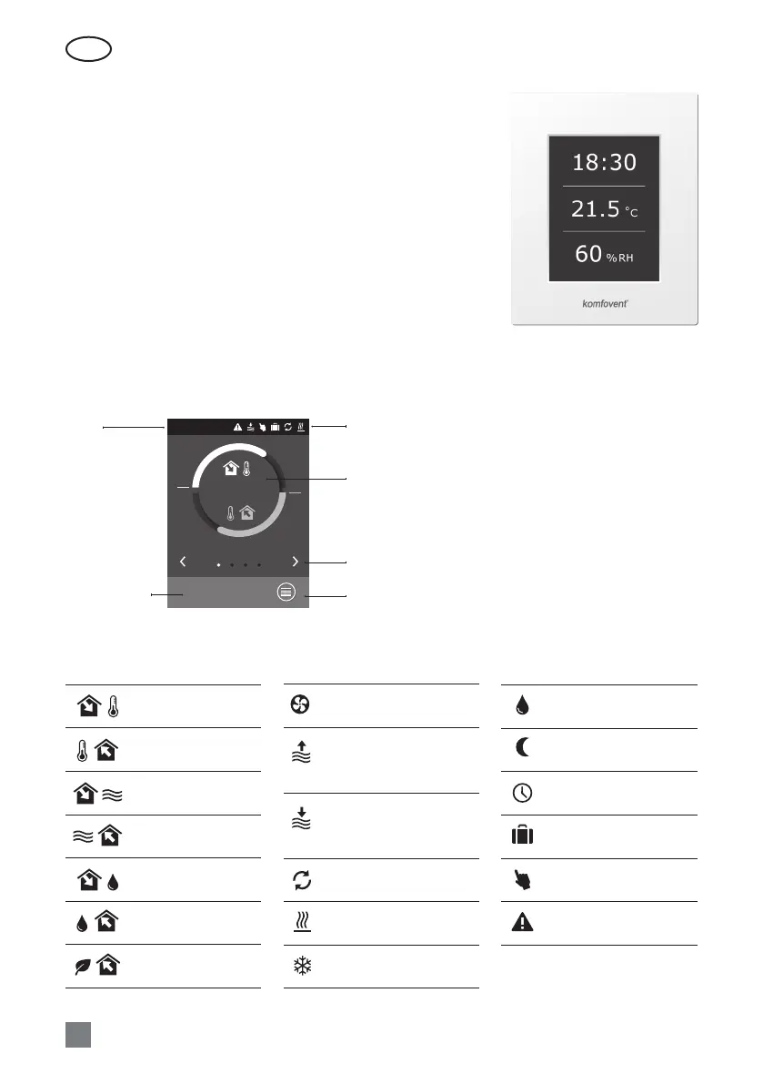
2.1 Picture. Control panel
2.2. Control panel indication
Supply air
temperature
Extract air
temperature
Supply air volume
Extract air volume
Supply air humidity
Extract air humidity
Extract (room)
air quality
Explanation of the displayed symbols
2. OPERATION MANUAL
2.1. Unit Control
Air handling units control system ensures control of the physical pro-
cesses that are taking place inside the air handling unit.
Control system consists of:
• main controller module;
• circuit breakers and main switch;
• control panel, which can be installed in the convenient place for the
user;
• pressure and temperature sensors.
Control panel (2.1 Picture) is designed for remote air handling unit
control, setting and display of controller parameters.
ECONOMY 1
21,9 °C
21,3 °C
Temperature
16:30
Selection of
operation modes
Menu
Indication of unit operation
modes and functions
Main parameters
overview window
Switching between
overview windows
Time