Page 15Page 14
5 Installation
5.1 Fitting Wheelpilot
With correct preparation, the Wheelpilot can be
installed in under an hour. However, it is impor-
tant that it is fitted correctly to operate to its max-
imum efficiency. Please read this section thor-
oughly before attempting installation.
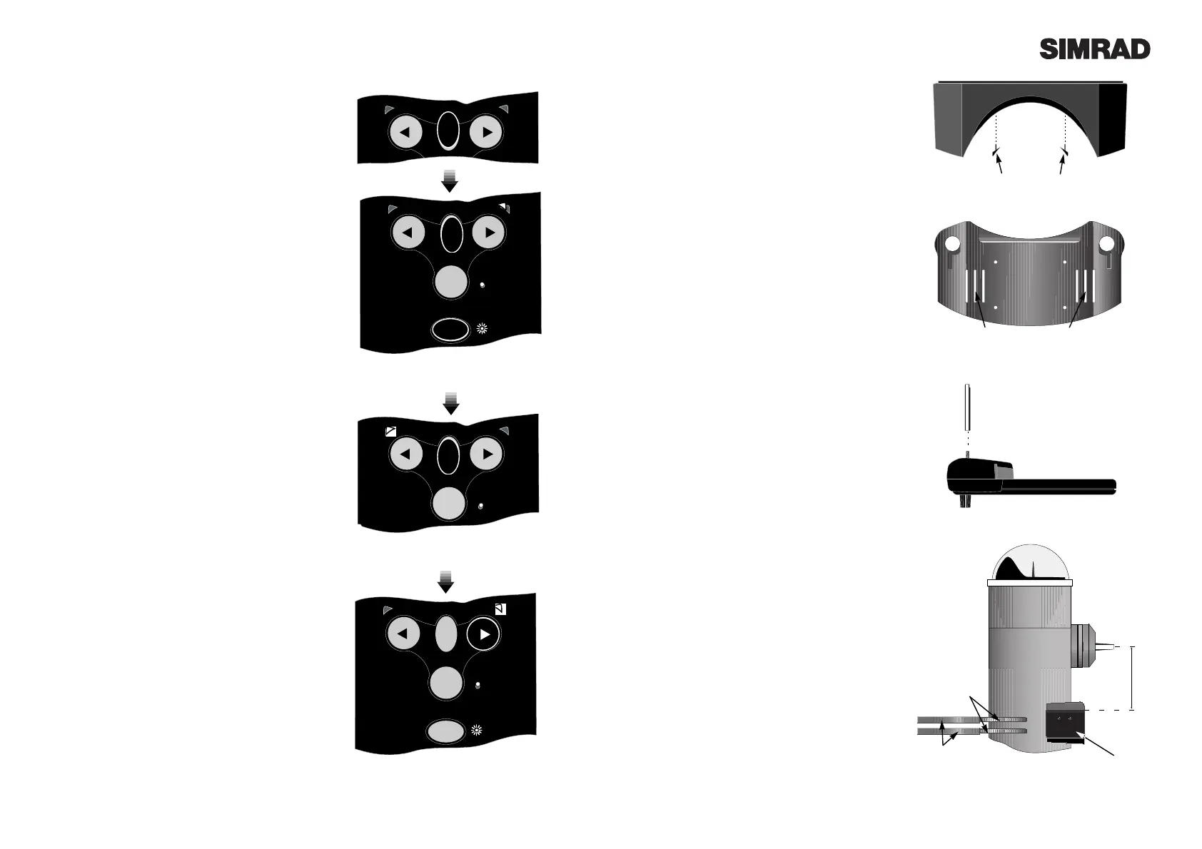
The fixing point of the Wheelpilot is the pedestal
mount which is fixed to the pedestal using two
band clamps. The Wheelpilot unit attaches to this
mount using two metal guide rods which slide into
slots on either side of the clamp. Thus, no holes
need to be drilled to install the pilot, and it can be
easily and quickly removed if necessary.
The pedestal mount supplied will fit most
pedestals 100 Ð 140mm (4.0 Ð 5.5 in) in diameter.
Two packing pieces are supplied for use with a
standard 100mm (4.0 in) pedestal (Fig 5.1). The
pedestal mount has three sets of slots for the band
clamps to suit the pedestal being fitted to (Fig 5.2).
For pedestals over 140mm (5.5 in) diameter, a larg-
er clamp is available as a separate accessory (part
code PED200:BK).
The two guide rods are not fitted to the Wheelpilot
itself when supplied and will need to be attached.
As these will support any loads the Wheelpilot is
subjected to it is important that they are securely
fitted. The ends of the rods have flats on them,
which will allow a 12mm spanner to be used to
tighten them (Fig 5.3).
1. Remove the wheel.
2. Position the pedestal mount on the front of the
pedestal. The vertical distance between the cen-
tres of the circular slots and the centre of the wheel
shaft should be 125mm (5.0 in) and the clamp
should be exactly parallel with the wheel in both
planes (Fig 5.4).
3. The exposed section of the band clamps are
slotted through the sleeving provided, which cov-
ers the clip and also prevents it from scratching
the pedestal when tightened. It is recommended
that the sleeving is cut approx 25mm (1.0in) short,
to prevent it from fouling the slots in the pedestal
mount through which the band clamps are fitted.
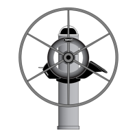
Fig 4.2 - Entering Calibration Mode
Fig 4.4 - Increasing Gain level
4.2 Calibration Mode
To adjust the Gain and Seastate settings of the
Wheelpilot it is necessary to enter Calibration Mode,
which can be done whilst the Wheelpilot is in either
Standby or Autopilot Mode.
Press and hold the TAC K key, followed by the NAV
key (Fig 4.2). The Starboard LED will illuminate to
indicate that the pilot is in Gain Mode. To toggle
between Gain and Seastate Mode, press the TACK
key (Fig 4.3). The Port LED will illuminate to indi-
cate Seastate Mode.
4.3 Adjusting Gain
When Gain Mode is selected (indicated by the
Starboard LED illuminated), the Nav LED will flash
and a repeated sequence of beeps will be heard. The
number of flashes and beeps in the sequence indi-
cates the level of the Gain setting.
To increase the Gain press the Starboard key the
required number of times, to a maximum level of 9
(Fig 4.4). To decrease the Gain press the Port key the
required number of times, to a minimum level of 1.
For example, if the Gain was set at 4 (indicated by a
sequence of four flashes of the Nav LED and four
beeps), and the Gain needed to be increased to 7,
pressing the Starboard key three times would adjust
the Gain accordingly. The Nav LED would then flash
seven times and seven beeps would be heard.
4.4 Adjusting Seastate
When adjusting Seastate (indicated by the Port LED
illuminated), the Seastate level is indicated by the
number of audible beeps and flashes of the Nav LED.
No beeps or flashes of the Nav LED indicates that the
Wheelpilot is set to automatic seastate (see section 2.7).
To switch from Auto to Manual Seastate and
increase the Seastate level, press the Starboard
key the required number of times to a maximum
level of 9. To decrease the Seastate press the Port
key the required number of times, to a minimum
level of 0 - which will switch the Wheelpilot back
to Auto Seastate.
To confirm Gain/Seastate settings and return to
normal operation, press the NAV key.
Fig 4.3 - Toggling between Adjust Gain and
Seastate
Fig 5.4 - Correct positioning of pedestal mount
Fig 5.3 - Attaching guide rods
Fig 5.1 - Fitting to 250mm (4.0 in) pedestal
Fig 5.2 - Rear view of pedestal mount
Slots for band clamps
Packing pieces
125mm (5.0 in)
Sleeving
Band clamps
Pedestal
Mount
 Loading...