


D
Douglas RiosSep 9, 2025
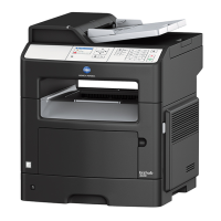
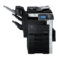
How to fix error message displayed on Konica Minolta All in One Printer?
- PPhilip NortonSep 9, 2025
If your Konica Minolta All in One Printer displays an error message, and documents stored in the memory are waiting to be printed, print them. If functions that cannot be used together are selected, make copies using only one of the functions. If the paper size of the document cannot be detected, select the paper size of the document. If some malfunction occurred in the machine, inform your technical representative of the code displayed on the touch panel.