EN68
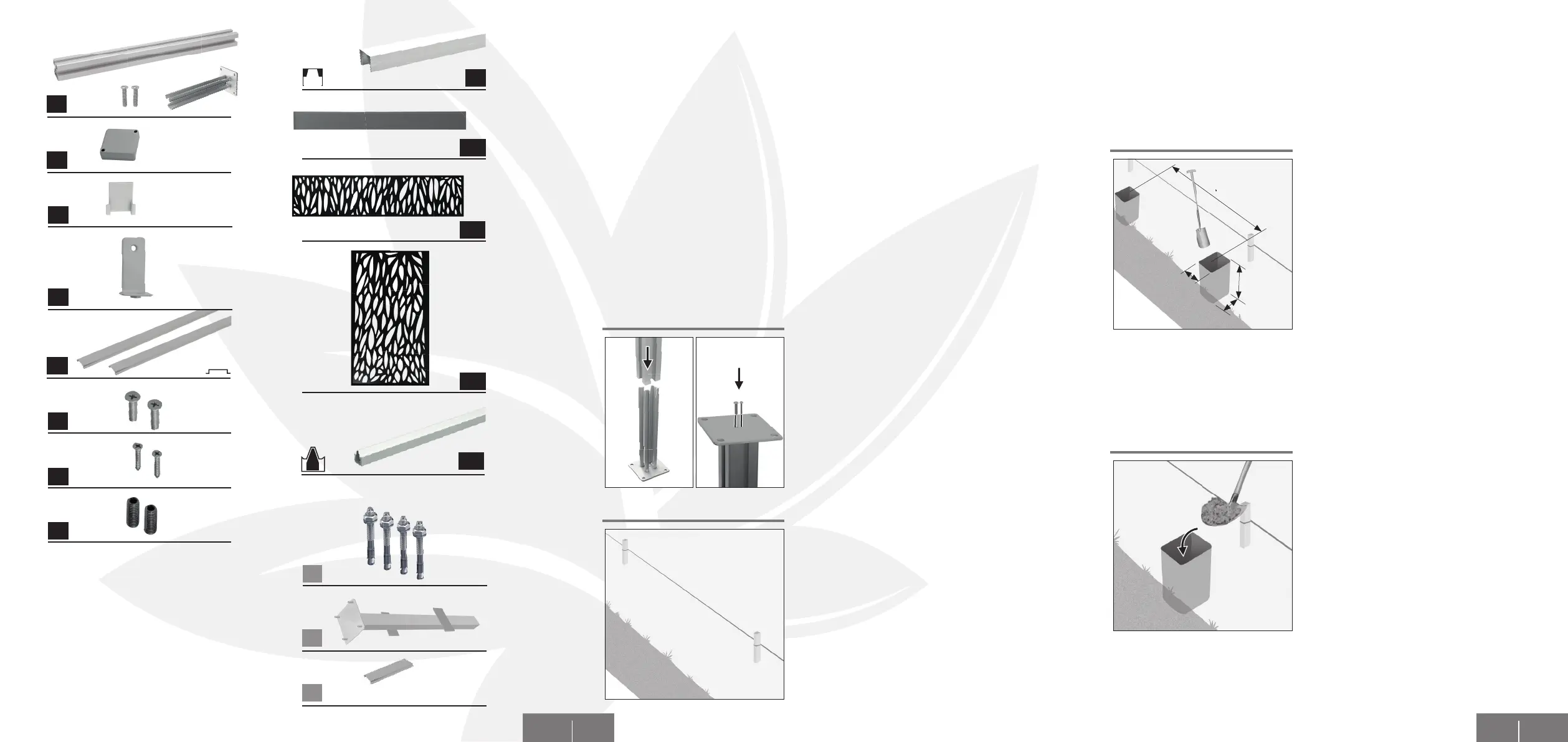
C omponents Observe the foldout pages!
Optionally available:
B1 Heavy-duty dowel
B2 Post anchor
B3 Height compensation for start pro le
Required Material
A1 Fence post and mounting bracket +
2x Base plate screws
A2 Post cap
Per fence post:
A3 2x L-Clip cover
A4 2x L-Clip
A5 2x Faceplate for fence post
1x Set of screws:
A6 2x Screws 5 x 20 mm
A7 2x Screws 3.5 x 20 mm
A8 2x Screws 8 x 20 mm
Per Fence element:
A9 1x End pro le
A10 max 13x fence panels
A11 1x Decorative element horizontal
A12 1x Decorative element vertical
A13 1x Start pro le
Span a cord along the planned course of
the fence. Take into account the di erences
in altitude of the terrain.
If a concrete foundation or a base wall
is provided, the fence posts can be xed
directly with an appropriate combination
of screws and dowels (e.g. a heavy-duty
dowel). In this case, please continue the
installation with step 5 on page 74.
Preparat ion
2
1
Preparing the fence post: Place the fence
post in the mounting bracket and screw
it into place on the underside using the 2
screws.
The fence posts can be alternately screwed
on directly or set in concrete with an anchor
(optionally available).
EN 69
Dig the holes for the post anchors with a
spade. The holes should have a dimension
of 350 mm x 350 mm and a depth of min.
700 mm. Please inform yourself about the
local depth of frost penetration.
Note: Keep the sod to eventually reinsert it
around the mounted post.
Fill concrete into the holes and compact it
with a timber beam! Use a spirit level to
ensure that the foundation is absolutely
level. Let the concrete harden thoroughly
(Observe the indications on the packaging).
Continue the installation with step 5 on
page 74.
If no concrete foundation or base wall is provided, concrete foundations can be prepared
beforehand. Please proceed as follows:
Fix posts directly with screws
3
4
700 mm
1805 mm
350 mm
350 mm
A1
B2
B3
A9
A2
A3
A4
A6
A7
A10
A8
A11
A12
A5
A13
B1