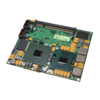
4 ETX® connectors
Kontron User's Guide ETX CD 20
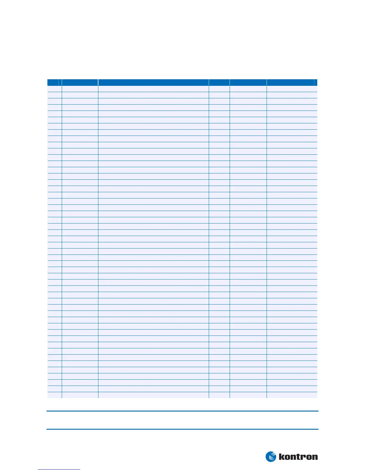
4.3.1 Connector X1 Signal Levels
Pin 1-50 [Power | PCI |USB | AUDIO]
Pin Si
1 GND Ground PWR - -
2 GND Ground PWR - -
3 PCICLK3 PCI Clock Slot 3 O-3,3 - -
4 PCICLK4 PCI Clock Slot 4 O-3,3 - -
5 GND Ground PWR - -
6 GND Ground PWR - -
7 PCICLK1 PCI Clock Slot 1 O-3,3 - -
8 PCICLK2 PCI Clock Slot 2 O-3,3 - -
9 REQ3# PCI Bus Re
uest 3 I-3,3 PU 8k2 3.3V 8k2 Ohm Resistors
10 GNT3# PCI Bus Grant 3 O-3,3 - -
11 GNT2# PCI Bus Grant 2 O-3,3 - -
12 3V Power +3,3V PWR - -
13 REQ2# PCI Bus Re
uest 2 I-3,3 PU 8k2 3.3V 8k2 Ohm Resistors
14 GNT1# PCI Bus Grant 1 O-3,3 - -
15 REQ1# PCI Bus Re
uest 1 I-3,3 PU 8k2 3.3V 8k2 Ohm Resistors
16 3V Power +3,3V PWR - -
17 GNT0# PCI Bus Grant 0 O-3,3 - -
18 nc - nc - Reserved
19 VCC Power +5V PWR - -
20 VCC Power +5V PWR - -
21 SERIRQ Serial Interru
IO-3,3 - 12mA Source sink
22 REQ0# PCI Bus Re
uest 0 I-3,3 PU 8k2 3.3V 8k2 Ohm Resistors
23 AD0 PCI Adress & Data Bus line IO-3,3 -
24 3V Power +3,3V PWR - -
25 AD1 PCI Adress & Data Bus line IO-3,3 - -
26 AD2 PCI Adress & Data Bus line IO-3,3 - -
27 AD4 PCI Adress & Data Bus line IO-3,3 - -
28 AD3 PCI Adress & Data Bus line IO-3,3 - -
29 AD6 PCI Adress & Da
a Bus line IO-3,3 - -
30 AD5 PCI Adress & Data Bus line IO-3,3 - -
31 CBE0# PCI Bus Command and B
te enables 0 IO-3,3 - -
32 AD7 PCI Adress & Data Bus line IO-3,3 - -
33 AD8 PCI Adress & Data Bus line IO-3,3 - -
34 AD9 PCI Adress & Data Bus line IO-3,3 - -
35 GND Ground PWR - -
36 GND Ground PWR - -
37 AD10 PCI Adress & Data Bus line IO-3,3 - -
38 AUXAL Auxiliar
I PD 4k7 ASGND 1:2 bleeder
39 AD11 PCI Adress & Data Bus line IO-3,3 - -
40 MIC Micro
I - -
41 AD12 PCI Adress & Data Bus line IO-3,3 - -
42 AUXAR Auxiliar
I PD 4k7 ASGND 1:2 bleeder
43 AD13 PCI Adress & Data Bus line IO-3,3 - -
44 ASVCC Analo
of Sound Controller O-5 - -
45 AD14 PCI Adress & Data Bus line IO-3,3 - -
46 SNDL Audio Out Lef
O - -
47 AD15 PCI Adress & Data Bus line IO-3,3 - -
48 ASGND Analo
Ground of Sound Controller P - -
49 CBE1# PCI Bus Command and B
te enables 1 IO-3,3 - -
50 SNDR Audio Out Ri
O - -
Note: The termination resistors in this table are already mounted on the ETX®board. Please refer to the design
guide for information about additional termination resistors.