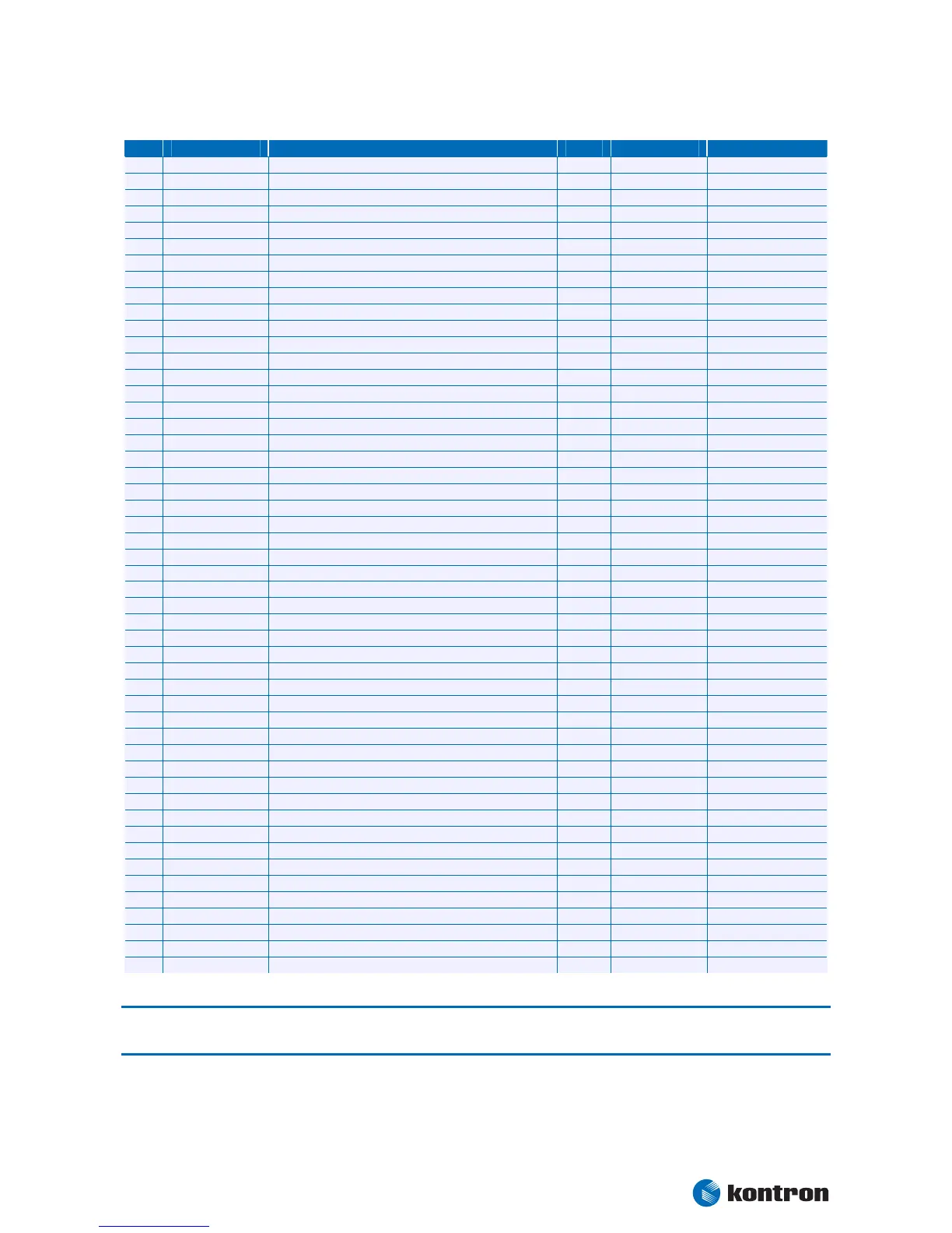
4 ETX® connectors
Kontron User's Guide ETX CD 30
Pin 51–100:
[Power | COM |LPT | Floppy | KB/MS/IR]
Pin Si
h: LPT, Low:
52 nc - nc - Reserved
53 VCC Power +5V PWR - -
54 GND Ground PWR - -
55 STB# | nc LPT Strobe Si
nal O-5 - -
56 AFD# | DENSEL LPT Automatic Feed
O-5 - -
57 nc - nc - Reserved
58 PD7 | nc LPT Data Bus D7 IO-5 - -
59 IRRX Infrared Receive I-5 - -
60 ERR# | HDSEL# LPT Error
IO-5 - -
61 IRTX Infrared Transmi
O-5 - -
62 PD6 | nc LPT Data Bus D6 IO-5 - -
63 RXD2 Data Receive COM2 I-5 PU 100k 5V -
64 INIT# | DIR# LPT Initiate
Direction O-5 - -
65 GND Ground PWR - -
66 GND Ground PWR - -
67 RTS2# Re
uest to Send COM2 O-5 PU 100k 5V -
68 PD5 | nc LPT Data Bus D5 IO-5 - -
69 DTR2# Data Terminal Read
COM2 O-5 PU 100k 5V -
70 SLIN# | STEP# LPT Selec
O-5 - -
71 DCD2# Data Carrier Detect COM2 I-5 PU 100k 5V -
72 PD4 | DSKCHG# LPT Data Bus D4
e IO-5 - -
73 DSR2# Data Set Read
COM2 I-5 PU 100k 5V -
74 PD3 | RDATA# LPT Data Bus D3
Raw Data Read IO-5 - -
75 CTS2# Clear to Send COM2 I-5 PU 100k 5V -
76 PD2 | WP# LPT Data Bus D2
nal IO-5 - -
77 TXD2 Data Transmit COM2 O-5 PU 100k 5V Bootstra
PU 4k7
78 PD1 | TRK0# LPT Data Bus D1
Indicator COM2 I-5 PU 100k 5V -
80 PD0 | INDEX# LPT Data Bus D0
nal IO-5 - -
81 VCC Power +5V PWR - -
82 VCC Power +5V PWR - -
83 RXD1 Data Receive COM1 O-5 PU 100k 5V -
84 ACK# | DRV LPT Acknowled
uest to Send COM1 O-5 PU 100k 5V Bootstra
IO-5 - -
87 DTR1# Data Terminal Read
COM1 O-5 PU 100k 5V Bootstra
PU 4k7
88 PE | WDATA# LPT Pa
Raw Write Data IO-5 - -
89 DCD1# Data Carrier Detect COM1 I-5 PU 100k 5V -
90 SLCT#|WGATE# LPT Power On
Write Enable IO-5 - -
91 DSR1# Data Set Read
COM1 I-5 PU 100k 5V -
92 MSCLK Mouse Clock O-5 PU 4k7 5V -
93 CTS1# Clear to Send COM1 I-5 PU 100k 5V -
94 MSDA
Mouse Data IO-5 PU 4k7 5V -
95 TXD1 Data Transmit COM1 O-5 PU 100k 5V Bootstra
board Clock O-5 PU 4k7 5V -
97 RI1# Rin
Indicator COM1 I-5 PU 100k 5V -
98 KBDA
board Data IO-5 PU 4k7 5V -
99 GND Ground PWR - -
100 GND Ground PWR - -
Note: The termination resistors in this table are already mounted on the ETX® board. Please refer to the design
guide for information about additional termination resistors.