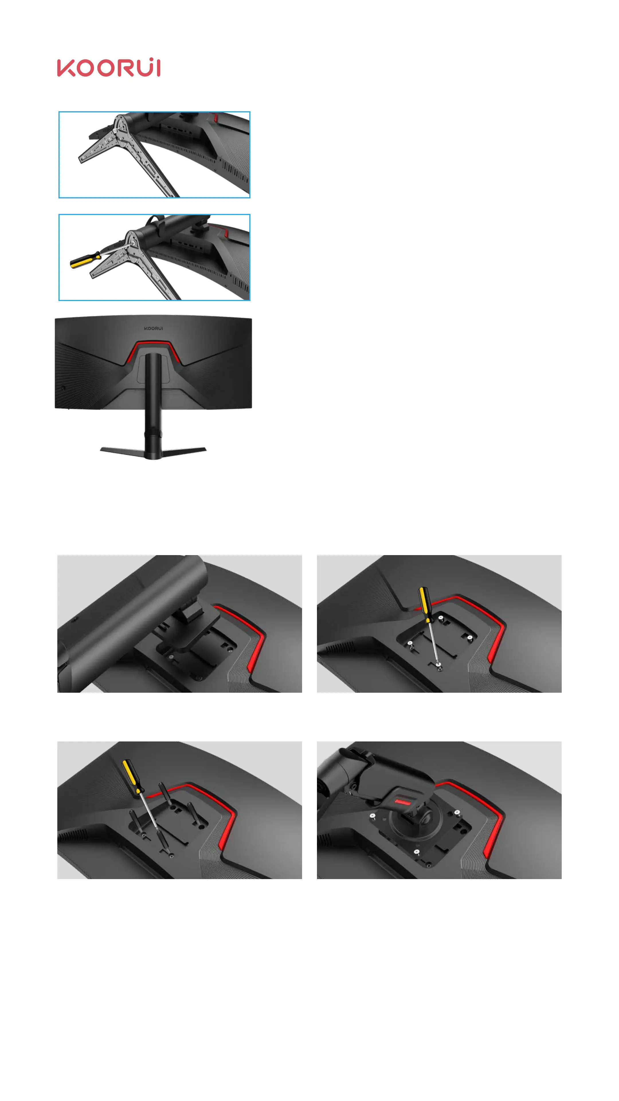
2.2.2 Installation Diagram of Holder Replacement with VESA Holder
Remove the original base of the product
(please ignore if the base is not installed)
Mount the screw post or use the VESA plastic
post (length not less than 24 mm).
Installation screws (use screw posts, please use the
rear shell screws removed in 2.2.2.1;The thread
length of the locked screw is 6-8mm if the screw
post is not used)
Remove the 4 screws here (retain the screws in
2.2.2.3; or use the original base bracket later)
Warning: The thread of the screw attached here exceeds 8mm, to avoid damage to the
interior due to excessive thread length.
The hole spacing in the wall mount is 75*75mm.
Insert the base into the column according to the
direction shown in the figure;
Use 2# cross screwdriver to tighten the screws
clockwise.
Check whether the base and the column are
firmly connected, and place the installed product
on a stable platform according to figure 1.5 -
monitor pick-and-place method.
05