6. Output Section
The Output Section provides several types of mono and quasi-stereo outputs. Most of the outputs are intended for use
with high-level (+4 dBm) studio and equipment, but the front panel VARIABLE Output provides a convenient interface
to musical instrument amplifiers and low-level (semi-pro) PA & recording equipment as well.
All outputs are unbalanced and can drive 600 ohms to full rated level (+21dBm max.).
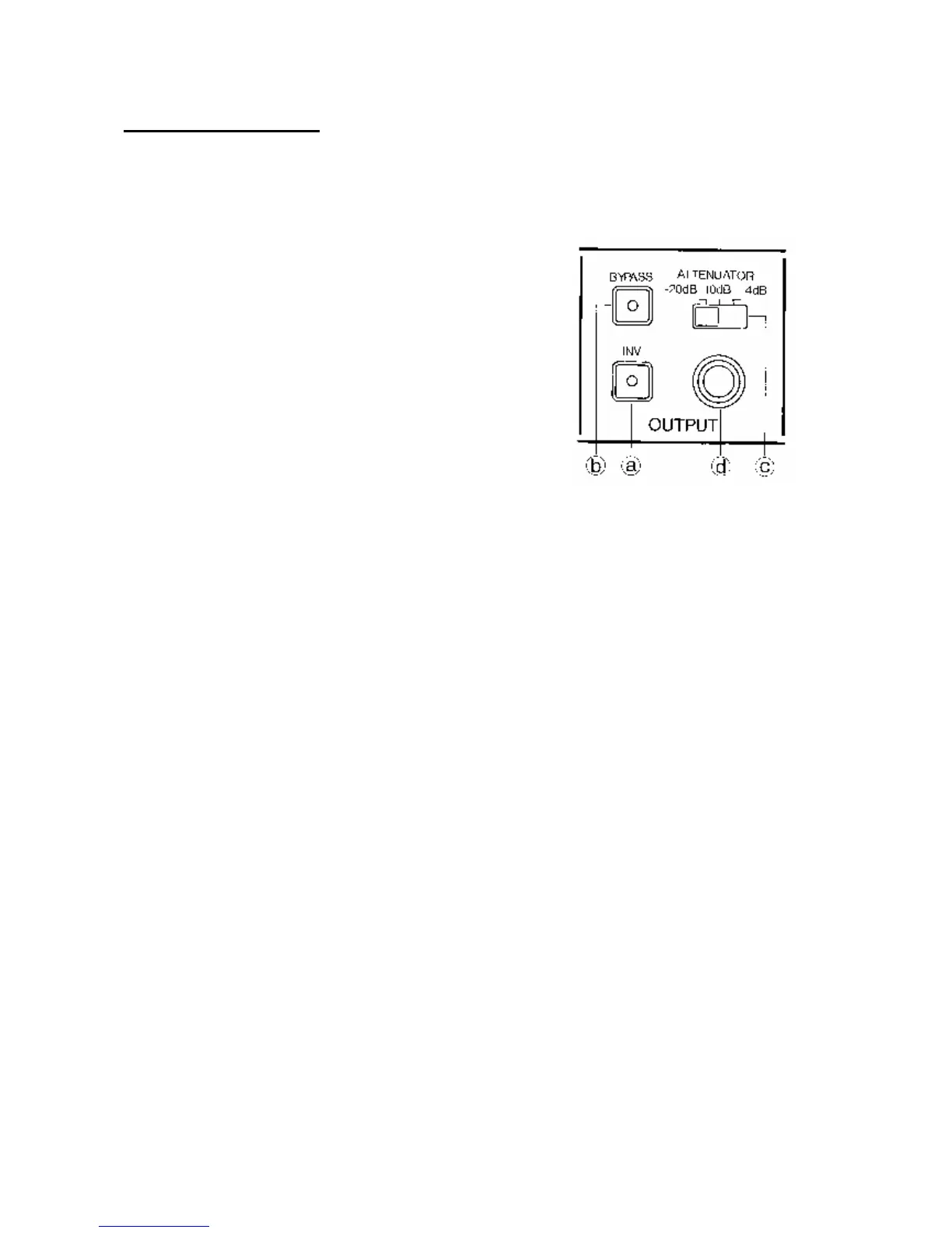
The Output Section contains the following:
a) INV button
b) BYPASS button & footswitch (Rear Panel - ? )
c) ATTENUATOR switch
d) VARIABLE Output Jack (Front Panel)
e) DIRECT Output Jack (Rear Panel - ? )
f) +MIX/MONO Output Jack (Rear Panel - ? )
g) -MIX Output Jack (Rear Panel - ? )
a) lNV Button
The Output INVert button inverts the phase of the Delayed signal in the output mix present al the front panel
VARIABLE and rear panel +MIX/ MONO Outputs only. The INV button does not effect the -MIX Output. Changing
the phase of the Output signal mix alters the tone quality of effects produced using short time delays.
Normally, the VARIABLE & +MIXI MONO Outputs provide the sum (in phase mix) of the Direct and Delayed signal.
With the Output INV button depressed (LED on), these outputs provide the difference (out-of-phase mix) of the Direct
and Delayed signal. The setting of the Output INV button is not programmable.
b) BYPASS Button & footswitch
The BYPASS button allows the selected effect to be turned on and off as desired. When the BYPASS LED is on, all
signal outputs will provide Direct signal only, regardless of the LEVEL BALANCE setting.
An optional footswitch (Korg PS-1, etc.) may be connected to the rear panel BYPASS jack for remote control of the
BYPASS function. The BYPASS button may still be used with the footswitch connected.
c) ATTENUATOR Switch
The ATTENUATOR switch selects the basic or "nominal" level of the VARIABLE Output jack. It should be set to a
position matching the input requirements of the equipment connected to the SDD-3000. in order to achieve best noise &
distortion performance. Equipment ranging from electric guitar amplifiers to professional studio mixers can be used
with excellent results. The Specifications section of this manual lists the different nominal and maximum output levels
that are available.
The rear panel Output jacks are not affected by the ATTENUATOR switch, but provide a nominal output level of
+4dBm at all times.
d) VARIABLE Output Jack (Front Panel)
The front panel VARIABLE Output jack provides a monaural mix of the Direct and Delayed signals, as determined by
the LEVEL BALANCE and Output INV controls. The nominal level at this jack is determined by the Output
ATTENUATOR switch, so that a variety of Equipment may be connected.
e) DIRECT Output Jack (Rear Panel - ? )
The DIRECT Output provides Direct signal only at all times, with no Delayed signal mixed in.
f) +MIX/MONO Output Jack (Rear Panel - ? )
The +MIX/MONO Output provides the sum (in-phase mix) or difference (Out of-phase mix) of the Direct and Delayed
signal. as determined by the Output INV button. The relative balance between Direct & Delayed signal is determined
by the LEVEL BALANCE control.
g) -MIX Output Jack (Rear Panel - ? )