Contents
1 Introduction 1
2 Getting Started 2
2.1 Quick Start 2
3 Overview 3
3.1 Shielded Twisted Pair/Unshielded Twisted Pair 3
3.2 Power Connect 3
4 Defining the 713/714 Video-Audio Line Transmitter/Receiver 4
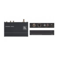
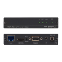
4.1 Defining the 713 Video-Audio Line Transmitter 4
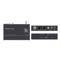
4.2 Defining the 714 Video-Audio Line Receiver 5
5 Connecting the 713 and 714 7
5.1 Automatic and Manual Equalization 8
5.2 Wiring the CAT 5 LINE IN/LINE OUT RJ-45 Connectors 9
6 Technical Specifications 10
Figures
Figure 1: 713 Video-Audio Line Transmitter Front and Rear Panels 4
Figure 2: 714 -05 Front and Rear Panels 5
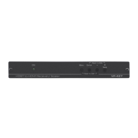
Figure 3: 714
-10 Video-Audio Line Receiver Front Panel 6
Figure 4: 714
-15 Video-Audio Line Receiver Front Panel 6
Figure 5: Connecting the Video-Audio Line Transmitter/Receiver System 7
Figure 6: CAT 5 PINOUT 9
Tables
Table 1: 713 Video-Audio Line Transmitter Front and Rear Panel Features 4
Table 2: 714-05/714-10/714 -15 Front and Rear Panel Features 5
Table 3: CAT 5 PINOUT 9
Table 4: Technical Specifications of the 713 and the 714-05/714-10/714 -15 10