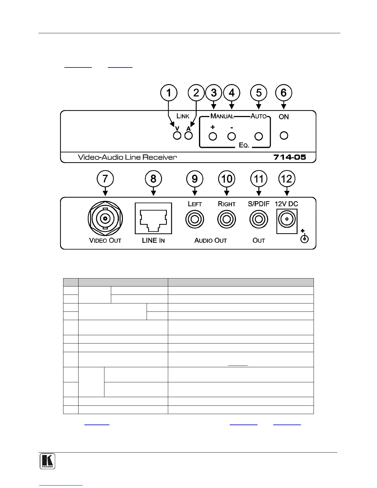
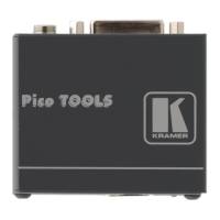
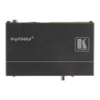
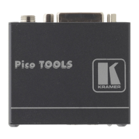
4.2 Defining the 714 Video-Audio Line Receiver
Figure 2 and Table 2 define the front and rear panels of the 714 Video-Audio Line
Receiver.
Figure 2: 714-05 Front and Rear Panels
Table 2: 714-05/714-10/714-15 Front and Rear Panel Features
1
LINK LED
V LED
Lights green when video link from the 713 is established
2 A LED
Lights green when audio link from the 713 is established
3
MANUAL EQ. Buttons
+ Press to increase the signal equalization
4 – Press to decrease the signal equalization
5 AUTO EQ. Button Press to reboot the device and set the equalization
automatically
6 ON LED Lights green when the unit is powered on
7 VIDEO OUT BNC Connector Connect to the composite video acceptor
8 LINE IN RJ-45 Connector
Connect to the LINE OUT RJ-45 connector on the 713
using CAT 5 cable (see
Figure 1)
9
AUDIO
OUT
LEFT RCA Connector Connect to the left channel of the unbalanced stereo audio
acceptor
10 RIGHT RCA Connector Connect to the right channel of the unbalanced stereo
audio acceptor
11 S/PDIF OUT RCA Connector Connect to the digital audio S/PDIF acceptor
12 12V DC Connector Connect to the supplied power adapter, center pin positive
Note: Table 2 also applies to the models shown in Figure 3 and Figure 4.