FC-101Net, FC-102Net – Defining FC-101Net and FC-102Net Dual Dante Interface
FC-102Net:
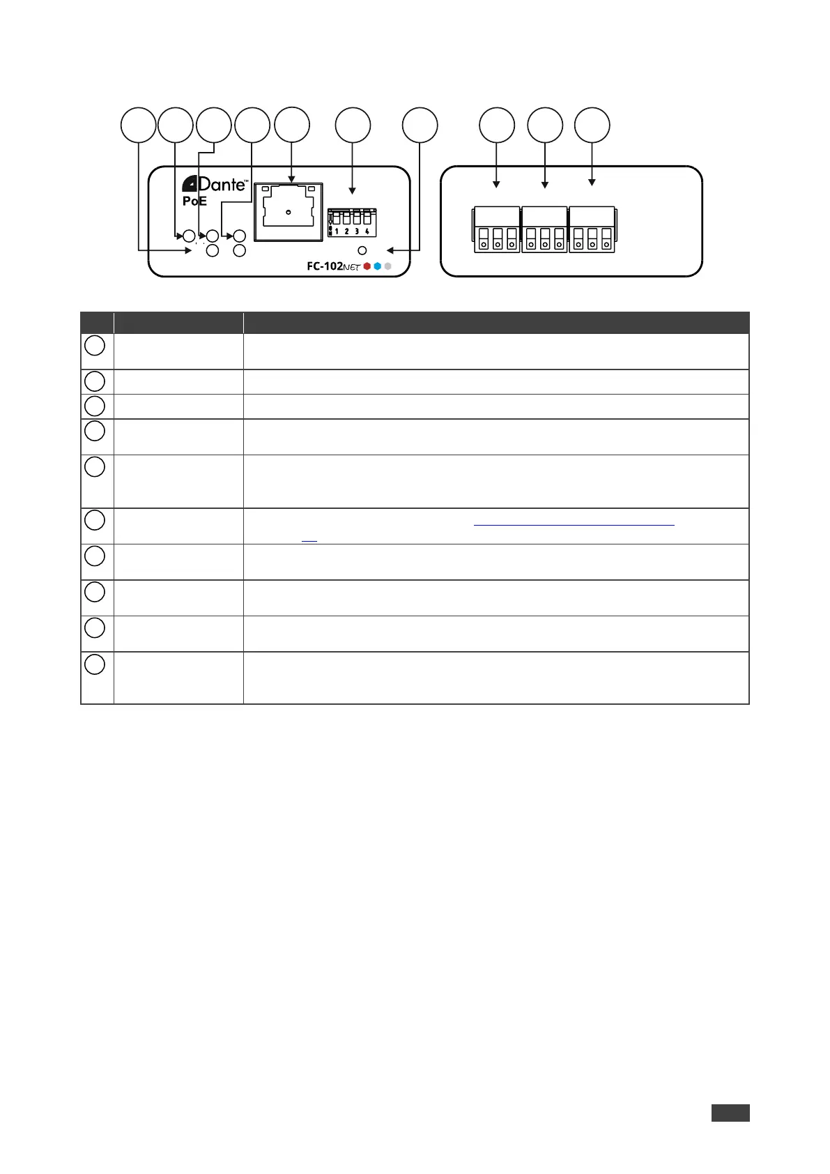
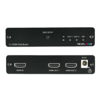
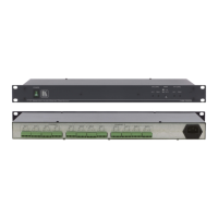
Figure 2: FC-102Net Dual Dante Interface Encoder
Lights white when a microphone is selected to the input (IN 1/IN 2); lights green
when a line level source is selected; lights red to indicate clipping on the input.
Lights green when the device receives power.
Lights green when Dante network is available; lights red if an error has occurred.
Lights green for digital audio normal operation; flashes green when this unit is
the Master clock; lights red if an error has occurred.
Connect to the Dante audio sink via the Network and provide Power over
Ethernet (PoE) to the device.
By default, DHCP is enabled.
Set the operation DIP-switches (see Setting FC-102Net DIP-switches
on page 10).
Press to reset to default parameters.
IN 1 3-pin Terminal
Block Connector
Connect to a balanced mono mic or line level source (+, –, G).
IN 2 3-pin Terminal
Block Connector
Connect to a balanced mono mic or line level source (+, –, G).
RS-232 3-pin
Terminal Block
Connector
Connect to a serial controller to control this device.
ON
IN1
Dual Dante Interface
SYS SYNC
IN2 DEF
SETUP
RS-232IN 1 IN 2
TxRxG
+
- G
+
- G
109 11 16141312 17 1815