KRAMER: SIMPLE CREATIVE TECHNOLOGY
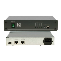
Using Your TP-400FW FireWire Range Extender
6
1. On each TP-400FW unit, connect
1
the power cord
2
and turn the unit ON.
(It is possible to connect the power cord to only one of the TP-400FW
units. The other TP-400FW units will derive their power from that unit).
2. Connect the CAT 5 Straight RJ45 connector on the first TP-400FW unit
to the CAT 5 Crossed RJ45 connector on the second TP-400FW unit, and
connect the CAT 5 Straight RJ45 connector on the second TP-400FW
unit to the CAT 5 Crossed RJ45 connector on the third TP-400FW unit
3
.
3. Connect a FireWire device (for example, a video camcorder) to the FW
PORT (R) on the first TP-400FW unit, and a FireWire device (for
example, a PC) to the FW PORT (F) on the third TP-400FW unit.
4. Be sure that the power on each device is turned ON.
The relevant CONNECTION STATUS green LEDs light (see items 2, 3, 4
and 5 in Table 1) as follows:
On the first TP-400FW unit, the STRAIGHT and the FW REAR LEDs
On the second TP-400FW unit, the STRAIGHT and the CROSSED LEDs
On the third TP-400FW unit, the CROSSED and the FW FRONT LEDs
Figure 4: Connecting 2 FireWire Devices via 3 TP-400FW Units (Extended 200m Range)
1 Not illustrated in Figure 4
2 We recommend that you use only the power cord that is supplied with this machine
3 Alternatively, connect the CAT 5 Crossed RJ45 connector on the first TP-400FW unit to the CAT 5 Straight RJ45
connector on the second TP-400FW unit, and connect the CAT 5 Crossed RJ45 connector on the second TP-400FW unit to
the CAT 5 Straight RJ45 connector on the third TP-400FW unit