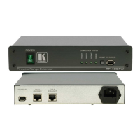
Using Your TP-400FW FireWire Range Extender
5
4. Be sure that the source and acceptor are powered-up (from their own power
supply or via the TP-400FW FireWire bus).
The relevant CONNECTION STATUS green LEDs light (see items 2, 3, 4
and 5 in Table 1).
Notes:
Apply the same rules for both source and destination FireWire equipment
(that is, first connect the power to both TP-400FW units and only then
connect the Firewire cables)
When reconnecting two TP-400FW units, first disconnect the cable, and
only then reconnect them
Wait 5 seconds (after completing all the connections) for the picture to
appear on the destination device. If the picture fails to appear on the
destination device after 5 seconds, press the RESET Button to reboot the setup.
Wait another 5 seconds for the picture to appear on the destination device
Figure 3: Connecting 2 FireWire Devices via 2 TP-400FW Units (Extended 100m Range)
5.2 Connecting 2 FireWire Devices via Several TP-400FW Units
You can interconnect multiple TP-400FW units to extend the FireWire range.
Each additional TP-400FW extends the range up to a further 100m. For
example, Figure 4 illustrates how three TP-400FW units may be used to extend
the FireWire range to 200m.
To interconnect three TP-400FW units using twisted pair UTP/CAT 5 cable
(commonly used for Ethernet connections), do the following: