Your TP-400FW FireWire Range Extender
3
4 Your TP-400FW FireWire Range Extender
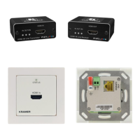
Figure 1, Table 1 and Table 2 define the TP-400FW:
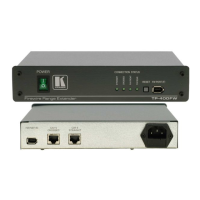
Figure 1: TP-400FW FireWire Range Extender
Table 1: Front Panel TP-400FW FireWire Range Extender Features
# Feature Function
1 POWER Switch Illuminated switch for turning the unit ON or OFF
2 STRAIGHT Lights when a connection is established using a CAT5 cable that connects
to the STRAIGHT RJ45 Connector
3 CROSSED Lights when a connection is established using a CAT5 cable that connects
to the CROSSED RJ45 Connector
4 FW FRONT
Lights when a connection is established between a fully functioning
FireWire device and the FireWire port on the front panel (item 7 in Table 1)
5
CONNECTION
STATUS
(Green) LEDs
FW REAR Lights when a connection is established between a fully functioning
FireWire device and the FireWire port on the rear panel (item 1 in Table 2)
6 RESET Button Reboots the setup (without having to disconnect and reconnect the power)
7 FW PORT (F) Connects to the FireWire device
Table 2: Rear Panel TP-400FW FireWire Range Extender Features
# Feature Function
1 FW PORT (R) Connects to the FireWire device
2 CAT 5 CROSSED RJ45 Connector Connects to the CAT 5 Straight connector on another
TP-400FW unit
3 CAT 5 STRAIGHT RJ45 Connector
Connects to the CAT 5 Crossed connector on another
TP-400FW unit
4 Power Connector with FUSE AC connector enabling power supply to the unit