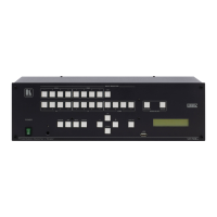
For the Ethernet connector, see the wiring diagram
below:
Changes to the DIP-switches only take effect on power-up. After
changing a switch, reboot the device. All DIP-switches are set to Off
(up) by default.
On (down) – Add IR modulation to the IR output
signal (applicable only when the IR port is
connected to an IR emitter cable).
Off (up) – Pass-through the IR signal (default)
to the IR port via an IR cable.
The IR Pass-through DIP-switch setup depends on the IR
control connectivity application and should be set to either Off
or On to ensure that the IR-controlled device responds to the
IR controller.
On (down) – Enable extra-range.
Off (up) – Disable extra-range (default).
Note that range mode affects the HDBT input only.
On (down) – Disable audio de-embedding.
Note that the audio output port is muted.
Off (up) – Enable audio de-embedding to the
analog audio output port (default).
For optimum range and performance use the recommended Kramer cables available at www.kramerav.com/product/VM-214DT.
Step 5: Connect the power
Connect the power cord to VM-214DT and plug it into the mains electricity.
Safety Instructions
There are no operator serviceable parts inside the unit.
Use only the power cord that is supplied with the unit.
Do not open the unit. High voltages can cause electrical shock! Servicing by qualified personnel only.
Disconnect the power and unplug the unit from the wall before installing.
See www.KramerAV.com for updated safety information.
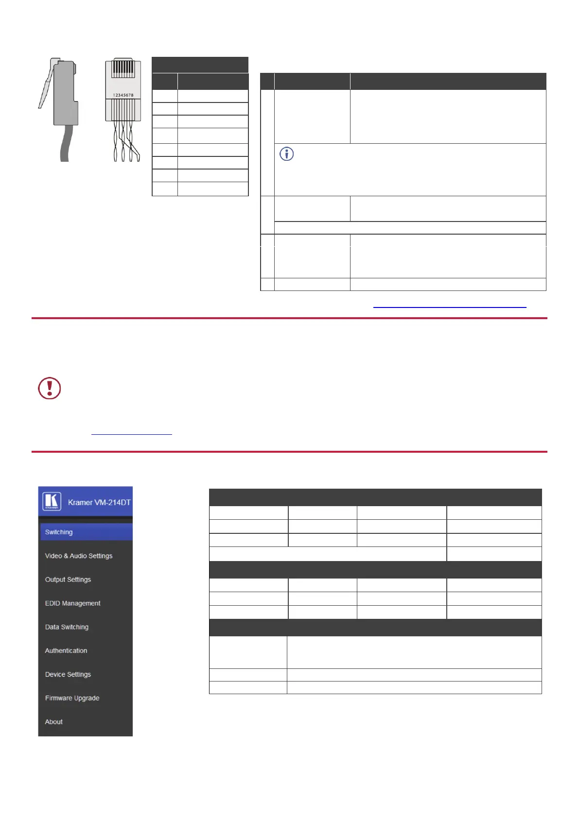
Step 6: Operate the VM-214DT
Example (Route input 1 to output 1):
Front panel buttons: power off the device, press and hold the
RESET button for 3 seconds while powering the device, and
then release.
In the Device Settings page, click Reset.
 Loading...