KRAMER: SIMPLE CREATIVE TECHNOLOGY
Connecting the VP-200XLT
16
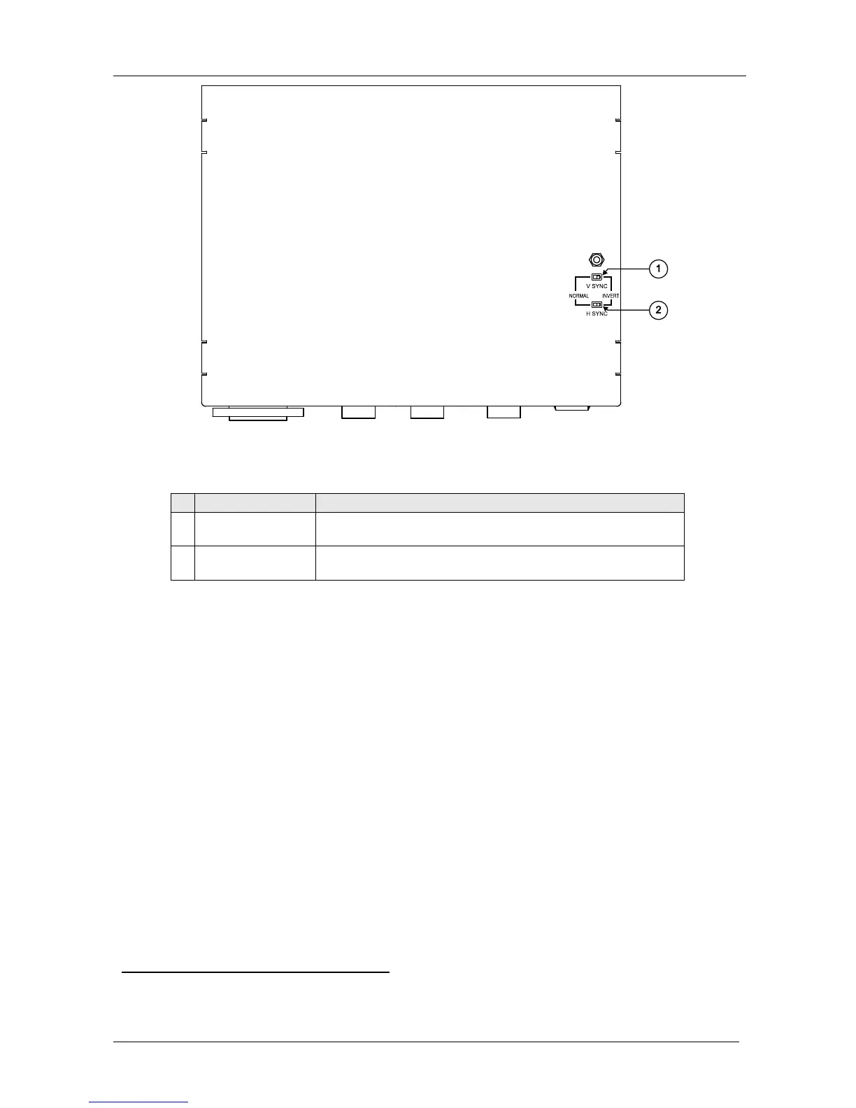
Figure 9: VP-5R CAT 5 Receiver / 1:5 VGA/UXGA Distributor (Underside)
Table 9: VP-5R CAT 5 Receiver / 1:5 VGA/UXGA Distributor (Underside) Features
# Feature Function
1 V SYNC Switch Slide the switch to the right
1
to change the V SYNC polarity;
slide the switch to the left to retain the polarity
2 H SYNC
Switch Slide the switch to the right
1
to change the H SYNC polarity;
slide the switch to the left to retain the polarity
9 Connecting the VP-200XLT
2
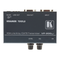
You can use the VP-200XLT and, for example, the TP-120 to configure an
XGA Line-to-Twisted Pair Transmitter and Receiver system.
To connect the VP-200XLT with the TP-120, as the example in Figure 10
illustrates, do the following:
1. On the VP-200XLT XGA Line Amp / CAT 5 Transmitter, connect the:
Computer graphics (XGA) source (for example, a
computer) to the INPUT 15-pin HD connector
XGA OUT 15-pin HD connector to the acceptor (for
example, to a projector)
2. On the TP-120 XGA Line Receiver, connect the XGA OUT 15-pin HD
connector to the XGA acceptor (for example, a display).
1 By default, both switches are set to the left
2 This section also applies to the VP-200XLTHD
 Loading...