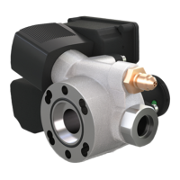
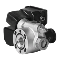
The KRIWAN Oil Level Regulator is a device designed to monitor and control the oil level in refrigerant compressors, ensuring optimal operation and preventing potential damage due to insufficient lubrication. This document provides comprehensive operating instructions, details on accessories, and application information for the product range of KRIWAN oil level regulators.
Function Description:
The primary function of the oil level regulator is to maintain an adequate oil level within the compressor. It operates on a closed-circuit principle, meaning the alarm relay picks up after a short delay (typically 3 seconds) if no malfunction is present. The device incorporates a solenoid valve that controls oil injection into the compressor.
For the INT280 B model, after power-on, a 20-second pause is initiated to allow oil to settle. If a low oil level is detected thereafter, the solenoid valve activates in a specified cycle: 5s fill/5s wait, then 10s fill/10s wait, and so on, with each subsequent cycle increasing the fill and wait times (e.g., 20s fill/20s wait). If an adequate oil level is not reached after 135 seconds, the alarm relay drops out, and the last filling cycle (approximately 30s fill/30s wait) remains active. Once the oil level is restored, the alarm relay picks up again after a waiting period, and the filling cycle resets. In case of a device malfunction (e.g., low supply voltage), the alarm relay drops out and locks after about 5 seconds, irrespective of the oil level, and no filling procedure is performed. This lock can be released by interrupting the voltage supply for at least 5 seconds.
The "INT280-xxx" models also initiate with a 3-second alarm relay pickup if no malfunction is present, followed by a 2-second pause for oil settling. If a low oil level is detected, the solenoid valve opens for a default filling time (10 seconds). If the desired level is not reached, the solenoid valve closes for a break time (default 20% of filling time, or 2 seconds) and then reopens for the filling time. This cycle continues until the fill level is adequate. If the oil deficiency alarm delay (default 120 seconds) expires before an adequate oil level is reached, the alarm relay drops out, but refilling attempts continue. The alarm relay picks up again once the oil level is restored. Device malfunctions (e.g., low supply voltage) cause the alarm relay to drop out and lock after approximately 5 seconds, with no filling procedure. These models feature an optical sensor monitoring system. Malfunctions are signaled by a flash code, locking the alarm relay. Soiling of the glass cone is also indicated by a flash code when a warning threshold is exceeded, though the function continues. If soiling reaches a critical value, the compressor may be switched off and locked, or a "warning soiling stage 2" may be generated, depending on the settings. The lock can be released by an open circuit of the voltage supply for at least 5 seconds.
The "INT280-xxx" models offer a diagnose port for reading out data such as the last 20 errors, error counters, current status, and switching behaviors using the INTspector. Various parameters can be adjusted for optimal adaptation, including:
- Filling cycle type: "fixed" uses set fill and break times; "adaptive" calculates optimal times based on a set nominal filling period number.
- Filling time: Duration the solenoid valve is open during an oil deficiency.
- Break time: Duration the solenoid valve is closed during an oil deficiency, specified as a percentage of the filling time.
- Overfill time: Duration the solenoid valve remains open after the oil level is reached.
- Set number of filling periods: For adaptive control, the regulator calculates times to achieve this number of filling times.
- Oil deficiency alarm monitoring: Option to evaluate the compressor run alarm delay.
- Oil deficiency alarm delay: Time started when oil deficiency is detected; if elapsed, the relay switches the compressor off.
- External alarm via DP bus: Allows an alarm from another Diagnose device to trigger the oil level regulator's alarm relay and LED.
- Operating recognition via DP bus: Setting to evaluate run detection from a connected Diagnose compressor protection unit.
- Behaviour monitoring: Setting to activate or deactivate behavior monitoring.
- Filling cycle time overrun coefficient: Generates a warning if the average filling cycle time (with DP bus run detection active) is exceeded during a filling process.
- Time overrun without filling coefficient: Generates a warning if the average time without filling process (with DP bus run detection active) is exceeded during compressor run.
- Soiling stage 2: Option to switch off the compressor if the second soiling stage of the glass cone is exceeded.
Important Technical Specifications:
The oil level regulators are designed for specific operating conditions.
- Permitted ambient temperature: -30...+100°C.
- Permitted relative humidity: 10-95% RH, without condensation.
- Operating pressure: max. 140 bar.
- Test pressure: max. 210 bar.
- Connection thread: Varies by adapter (e.g., 1 1/8"-12 UNF, 1 1/8"-18 UNEF, 3/4"-14 NPT, 1 3/4"-12 UNF, 1 1/4"-12 UNF).
- Flange mounting: Uses M6x20 Class 8.8 DIN 933 screws, DIN EN ISO 7089-6-St washers, DIN 6798-A 6.4-FSt toothed gear, and EPDM seal.
- Tightening torque: 9 Nm for flange mounting.
- Material: Steel, nickel-plated.
- Permissible media: Oils and refrigerants that do not attack the adapter material.
- Weight: Approximately 300g for the adapters.
- Electrical connection: Specifics are detailed in separate data sheets, including voltage supply (115V and 24V versions require correct supply voltage). Separate isolation switches are necessary.
- DP cable connections: "INT280-xxx" Diagnose models can operate with data from INT69 Diagnose compressor protection units via a DP-Y cable (KRIWAN original DP cables must be used with INT600 DM networks). DP cables must not be modified or extended and should only be connected/disconnected when there is no voltage.
Usage Features:
- Intended Use: Monitors and controls oil levels in refrigerant compressors. Adapters (e.g., INT280 adapters) connect the regulator to various compressor sight glass designs.
- Installation: The device must be mounted horizontally to the compressor, with the sight glass pointing left or right. It can be rotated by 180°. An O-ring must be properly seated at the connecting flange. Matching washers should be used for flange fastening screws. For low-temperature applications, an oil sump heater is recommended. An oil filter in the oil infeed line is crucial to prevent solenoid valve seat contamination.
- Cable Installation: Cables must be routed with appropriate bending radius, fixed at sufficient distances, and include a drip loop. Approved cable cross-sections ensure the seal of PG screw fittings.
- Commissioning: Before initial power-on, the oil level should be at least 1/4 of the sight glass to prevent immediate alarm deactivation. The refrigerating system and regulator connections must be checked for leaks before filling with refrigerant.
- Misuse Prevention: Operation in explosive or flammable areas is prohibited. Modifications to the device are not permitted. Only manufacturer-supplied spare parts and accessories should be used to ensure operational safety.
- Operator Limitations: Normal operation requires trained personnel; maintenance and repair require trained, qualified personnel.
Maintenance Features:
- Inspection: KRIWAN oil level regulators are maintenance-free, with no fixed inspection intervals. However, during other system inspections, the following points can be checked:
- Completeness and mechanical integrity of the regulator.
- Oil level in the sight glass (should be at least half).
- Proper mounting and sealed connections (tighten screws if necessary).
- Maintenance: The device itself is maintenance-free. If a malfunction occurs, the oil level regulator should be replaced.
- Cleaning:
- INT280 B: No special cleaning measures are necessary. The functional parts of the regulator cannot be cleaned; replace the unit if there's a malfunction.
- "INT280-xxx": If the regulator signals soiling, it can be removed, and the glass prism can be cleaned with a soft cloth. This requires switching off the system voltage, evacuating the refrigerant compressor, depressurizing the oil connection, removing the regulator, cleaning the prism, and then reassembling. Work on electrical and pneumatic equipment must be carried out by authorized electricians and refrigeration technicians, respectively, ensuring the system is depressurized and de-energized beforehand.
- Disposal: All components must be disposed of according to national recycling regulations. Electrical scrap metal, marked with the European directive 2002/96/EU symbol, must be disposed of separately from household garbage via local municipal authorities.