Do you have a question about the KROHNE H250 M10 and is the answer not in the manual?
These additional instructions complement standard documentation for explosion-protected versions.
Declares conformity with the protection goals of Directive 94/9/EC for use in hazardous areas.
Assembly, installation, start-up and maintenance may only be performed by personnel trained in explosion protection.
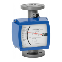
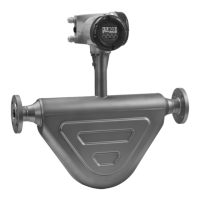
Measures and displays the volume flow of flammable and non-flammable gases and liquids.
Explains the elements that constitute the safety description code.
Details type designation, nameplates, and additional markings on the housing cover.
Defines explosive atmosphere conditions and provides operational warnings.
Specifies design according to EN standards for use in zone 1.
Details flameproof enclosure 'd' design and its associated marking interpretation.
Explains how product and ambient temperatures determine the device's temperature class.
Provides rated voltage and nominal current for electrical equipment.
Installation and setup must be carried out by qualified personnel according to applicable standards.
Covers equipotential bonding and electronics compartment lock requirements.
Details insulation ratings, terminal compartment, and cable connection requirements.
The required supply for built-in electronics is provided via the 4...20mA current output.
Connecting signal circuits to PELV devices and terminal assignment details.
Connecting the signal converter to the equipotential bonding system of the hazardous area.
Outlines conditions for permitted start-up and configuration methods.
Operating within limits and safety measures for flammable products.
Recommends checks for housing, cable entries, connections, and indicator for proper condition.
Procedures for opening the electronics compartment and replacing components.
| Type | Variable area flowmeter |
|---|---|
| Process Pressure | Up to 40 bar |
| Power Supply | 24 V DC |
| Application | Liquids and gases |
| Nominal Diameter | DN15 to DN150 |
| Pressure Rating | PN40 |
| Fluid Conductivity | Not required |
| Output Signal | 4…20 mA, HART® |
| Protection Class | IP67 |
| Material | Stainless steel, PTFE |
| Approvals | ATEX, IECEx |
| Process Temperature | -40 to +150°C |