Do you have a question about the KROHNE SU 600 Ex and is the answer not in the manual?
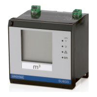
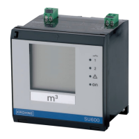
The KROHNE SU 600 Ex is a universal signal conditioning instrument and power supply unit designed for connection of a 4...20 mA/HART sensor. It is suitable for use in explosion-endangered areas, being an intrinsically safe instrument. The device provides continuous sensors with integrated level switches and a display for continuous sensors. It can serve as a power supply unit for the connected sensor and is designed for connection to any 4...20 mA sensor. The instrument is suitable for carrier rail, panel, and surface mounting.
The SU 600 Ex signal conditioning instrument processes and displays measurement signals from connected sensors. It converts the measured variable into a remote indication or a superior-directing control system. The device features two level relays for control of pumps or other devices. The instrument is operated via integrated keys and a 16-step function switch.
The device offers various functionalities, including:
The SU 600 Ex can operate in two modes:
The instrument features an integrated display and adjustment unit. The LC display shows the measured value, adjustment, and diagnosis. A function switch and two keys are used for operation.
General Data:
Voltage Supply:
Sensor Input:
Relay Outputs:
Current Output:
Indicators:
Ambient Conditions:
Electrical Protective Measures:
Electrical Separating Measures:
Dimensions:
Mounting: The SU 600 Ex is designed for recessed installation in a front panel, housing front plate or a switching cabinet door. It requires a cutout of 92 x 92 mm (3.63 x 3.63 in). The protection rating IP 40 is guaranteed when installed correctly. The instrument can be mounted into a switching cabinet or housing by means of three screws (fixed with screws on rear of housing). A mounting adapter for carrier rail mounting is optionally available.
Front panel mounting:
Screw mounting:
Carrier rail mounting:
Connecting to Power Supply: The SU 600 Ex is connected using standard two-wire cable without screen. Electromagnetic interference is expected which is above the test values of EN 61326 for industrial areas, screened cable should be used. The cable screen must be connected directly to the internal ground terminal. The ground terminal cable on the sensor housing must be connected to the potential equalisation.
Setup and Adjustment: The integrated display and adjustment unit is used for measured value display, adjustment, and diagnosis. The LC display and the adaptation of the relay switching points are further settings. Additional setup steps would be, if necessary, setting an integration time (damping) to steady the measured value or modifying the current output characteristics.
Switch-on phase: After being switched on, the SU 600 Ex carries out a self-check. The following steps are carried out:
Measured value indication: The measured value indication shows the digital indication value and also an analogue bargraph. The function switch is set to position 0 ("OPERATE").
Function switch: The following functions can be selected via the rotary switch:
Offset correction: When a pressure transmitter is used, an offset correction should be carried out first. These instruments are factory-set in a certain position. If the pressure transmitter is now mounted in a different position, its measuring range is shifted slightly. The zero point is readjusted by carrying out the offset correction in uncovered (unpressurised) conditions.
Adjustment in mA without changing the level: For this adjustment procedure, two sensor current values (4...20 mA) must be entered corresponding to the levels 0 % and 100 %.
Adjustment in % by changing the level: During this adjustment procedure, the current level is assigned to a certain percentage value. For this reason, percentage values that correspond to the actual filling levels must be entered for the min. and max. adjustment. The ideal calibration is at 0 % and 100 %. Because it is not always possible to empty or fill a vessel completely, any value can of course be entered. The greater the difference between the two adjustment points, the more precise the measurement. It does not matter which value is entered first.
Relay outputs: Two operating relays are integrated. The relays should switch on and off again. If there are two relays, you have to distinguish between the relay modes overfill and dry run protection. You switch over by exchanging the ON/OFF values of the relay.
Scaling: Scaling means converting the measured value into a certain parameter and unit. The indication can then show the volume in litres, instead of the percentage value. Indication values from -9999 to +9999 are possible.
Damping: To suppress fluctuations in the measured value display, e.g. caused by an agitated product surface, an integration time can be set. The time can be between 0 and 250 seconds. Remember that the reaction time of the entire measurement will then be longer and the sensor will react to measured value changes with a delay.
Current output 0/4...20 mA: The characteristics of the current output can be switched over from 4...20 mA to 0...20 mA.
Simulation: The settings of SU 600 Ex are correct, the simulation mode can be used. Any individual measured value can be simulated and e.g. the correct behaviour of the relays and the connected instruments can be checked.
Reset: With a reset, all values set by the user will be lost and are reset to factory settings.
Maintenance: If the instrument is used properly, no special maintenance is required in normal operation.
Rectify Faults: The operator of the system is responsible for taking suitable measures to rectify faults. Maximum reliability is ensured. Nevertheless, faults can occur during operation. These may be caused by:
The first measures to be taken are to check the input/output signals as well as to evaluate the error messages via the display. The procedure is described below. In many cases, the causes can be determined in this way and faults can be rectified.
Fault message: The signal conditioning instrument and the connected sensors are permanently monitored during operation and the values entered during parameter adjustment are checked for plausibility. If irregularities occur or in case of incorrect parameter adjustment, a fault signal is triggered. In case of an instrument defect or line break/shortcircuit, a fault signal is also triggered. The fail safe relay deenergises in case of failure, the failure indication lights and the current output jumps to 22 mA. In addition, one of the following fault messages is outputted on the display.
| Error code | Cause | Rectification |
|---|---|---|
| E003 | CRC error (error with self-check) | – Carry out a reset – Send instrument for repair |
| E014 | Sensor current > 21 mA or short-circuit | – Check sensor, e.g. on failure – Remove short-circuit |
| E015 | Sensor in boot phase Sensor current < 3.6 mA or line break |
– Check sensor, e.g. on failure – Remove line break – Check connection of the sensor |
| E016 | Empty/full adjustment reversed | – Carry out a fresh adjustment |
| E017 | Adjustment span too small | – Carry out a fresh adjustment and increase the distance between min. and max. adjustment |
| E21 | Scaling span too small | – Carry out a fresh scaling, increase the distance between min. and max. scaling. |
| E110 | Relay switching points too close together | – Increase the difference between the two relay switching points |
Instrument repair: If a repair is necessary, please proceed as follows:
Disposal: The instrument consists of materials which can be recycled by specialised recycling companies. We use recyclable materials and have designed the parts to be easily separable. This instrument is not subject to the WEEE directive 2002/96/EG and the respective national laws. Pass the instrument directly on to a specialised recycling company and do not use the municipal collecting points. These may be used only for privately used products according to the WEEE directive. Correct disposal avoids negative effects on humans and the environment and ensures recycling of useful raw materials.
| Brand | KROHNE |
|---|---|
| Model | SU 600 Ex |
| Category | Measuring Instruments |
| Language | English |