EasyManua.ls Logo

KROHNE UFC 300 V2 - User Manual

KROHNE UFC 300 V2
56 pages
Print Icon
To Next Page IconTo Next Page
Loading...
Signal converter for ultrasonic flowmeters
Description of PROFIBUS interface
Description of PROFIBUS interfaceDescription of PROFIBUS interface
Description of PROFIBUS interface
PROFIBUS PA:
PROFIBUS PA:PROFIBUS PA:
PROFIBUS PA:
PROFIBUS device with MBP Physical Interface and PA Profile 3.02 (V1.0.0_ / 200407)
PROFIBUS DP:
PROFIBUS DP:PROFIBUS DP:
PROFIBUS DP:
PROFIBUS device with RS485 Physical Interface and PA Profile 3.02 (V1.0.0_ / 200407)
UFC 300 V2
UFC 300 V2UFC 300 V2
UFC 300 V2
Supplementary Instructions
Supplementary InstructionsSupplementary Instructions
Supplementary Instructions
© KROHNE 07/2021 - 4008384701 - AD UFC300 V2 Profibus R01 en
The documentation is only complete when used in combination with the relevant
documentation for the flow sensor.
Question and Answer IconNeed help?

Do you have a question about the KROHNE UFC 300 V2 and is the answer not in the manual?

Overview

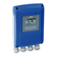
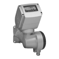
The UFC 300 V2 is a signal converter designed for ultrasonic flowmeters, featuring PROFIBUS PA and PROFIBUS DP interfaces. It supports the PROFIBUS PA Profile 3.02, ensuring standardized parameters and functions for process control applications.

Function Description

The device acts as an interface between ultrasonic flowmeters and a PROFIBUS network, enabling both cyclic and acyclic communication services. It translates measurement data from the flow sensor into a format compatible with PROFIBUS, allowing for integration into control systems (e.g., PLCs) and engineering tools (e.g., DD/DTM based tools).

The UFC 300 V2 implements a function block application model, grouping parameters and functions into different blocks:

  • 1 Physical Block (PB): Contains identification and diagnosis parameters of the device.
  • 1 Flow Transducer Block (TB): Manages parameters and functions related to flow measurement.
  • 6 Analog Input Function Blocks (AI-FB): Controls measuring outputs and provides measurement values. These blocks are assigned to slots 1, 2, 6, 7, 8, and 9.
  • 3 Totalizer Function Blocks (TOT-FB): Manages and provides counter values. These blocks are assigned to slots 3, 4, and 5.

The Analog Input and Totalizer Function Blocks serve as the primary data interfaces for process control systems, allowing their input/output data to be read or written via cyclic communication.

Important Technical Specifications

PROFIBUS DP Interface:

  • Type: PROFIBUS RS485 interface according to IEC 61158-2.
  • Connection: Polarity-dependent.
  • Device Profile: PROFIBUS PA Profile 3.02; conformance class B, compact.
  • Address Range: 0...126 (default 126). Can be set via PROFIBUS service set_slave_add (0...125) or local display (0...126). Address 126 is also the default for factory reset.
  • Local Control: Local display and operator interface on the device.
  • SAPs: 2 x MS1 SAPs (acyclic interface to PLC), 3 x MS2 SAPs (for master class 2 tools).
  • GSD Files: Supports KR014522.GSD and PA039741.GSD. KR014522.GSD provides complete functionality, while PA039741.GSD is for profile-specific functionality with reduced features.
  • Baud Rate: Supports various baud rates listed in the GSD file. Automatic baud rate search is active after power-on or PROFIBUS timeout.

PROFIBUS PA Interface:

  • Type: PROFIBUS MBP interface according to IEC 61158-2 with 31.25 kbits/s; voltage mode (MBP = Manchester Coded Bus Powered).
  • Connection: Polarity-independent.
  • Base Current: 10.5 mA.
  • FDE (Fault Disconnection Electronics): Yes, separate fault disconnection electronics provided.
  • Fault Current: 6 mA (max. continuous current - base current).
  • Starting Current: <12 mA.
  • Ex Approval: Ex ia IIC or Ex ib IIC/IIB, FISCO Device.
  • GSD Files: Supports KR014523.GSD and PA139741.GSD. KR014523.GSD provides complete functionality, while PA139741.GSD is for profile-specific functionality with reduced features.

Cyclic Data Transfer:

  • Input data (measurement and totalizer values) are transferred as 4-byte float values (IEEE Standard 754 Short Real Number) and 1-byte status values.
  • Output data controls totalizers, including SetTot (reset/preset totalizer) and ModeTot (totalization mode).

Diagnosis:

  • The device performs internal self-tests, providing detailed diagnosis information according to PA Profile 3.02.
  • Diagnosis information is bitwise coded and available via engineering tools or cyclic services.
  • Supports "Condensed Status and Diagnosis" (default, for newer systems) and "Classic Status and Diagnosis" (for backward compatibility).
  • The IDENT_NUMBER_SELECTOR parameter (slot 0, index 40) allows selection of the Ident. Number, influencing the amount and content of diagnosis information and transferred measuring values.
    • Automatic adaptation mode (factory setting): Device selects operation mode based on the GSD file during start-up.
    • Manufacturer specific Ident. Number (4522 hex for DP, 4523 hex for PA): Provides complete functionality, including device-specific diagnosis.
    • Profile specific Ident. Number (9741 hex for DP, 9741 hex for PA): Reduced functionality to mandatory PA Profile requirements, improving interchangeability.
  • Diagnosis events are categorized into "Event groups" (e.g., F- (Failure), S- (Out of specification), M- (Maintenance required), C- (Function check), I- (Information)), each consisting of up to 32 "Single events".
  • "Single events" can be filtered (disabled) to prevent them from setting the diagnosis bit of their associated "Event group". This filtering is only possible via PROFIBUS DTM or EDD tools, not via the local display.

Usage Features

  • Parameter Configuration: Units for local display and PROFIBUS transfer can be set separately. A master class 2 tool is required to modify units for PROFIBUS transfer.
  • Function Block Configuration: During network configuration, users define which function block outputs are transferred cyclically to the master. This is done via a bus configuration tool.
  • Totalizer Control: Totalizers can be reset, preset, or stopped via output data. Various totalization modes are available, including summing positive and negative values, only positive values, only negative values, or stopping totalization.
  • Analog Input Block Control: Measurement values for analog input blocks can be selected (e.g., Volume Flow, Mass Flow, Temperature), and time constants can be set.
  • Error Behaviour: For analog input blocks, error behaviour can be configured as "hold value" (last valid value used), "ignore error" (continue with bad status values), or "replace value" (use a predefined replacement value).
  • Display Menu: The local display menu allows for quick setup (A, Quick Setup), testing (B, Test), and detailed configuration (C, Setup, D, Service).
    • A, Quick Setup: Allows setting the Tag descriptor, resetting errors, resetting totalizers, and setting the PROFIBUS station address.
    • B, Test: Provides information about the PROFIBUS interface, including hardware/software versions and compilation date.
    • C, Setup: Offers detailed configuration for process input (diagnostics classification), totalizers (function, measurement, unit, preset value, reset, error behaviour), and analog input blocks (measurement, time constant, error behaviour, replacement value).
    • D, Service: A protected menu requiring a service password, allowing for identification number selection, PROFIBUS cold start, and resetting diagnosis extension history.

Maintenance Features

  • Diagnosis Information: Detailed diagnosis messages are available via the device display menu ("Test → Information → Status Details") or engineering tools, providing insights into various issues such as hardware failures, measurement failures, maintenance requirements, and configuration errors.
  • Error Reset: Errors can be reset via the "Reset Errors" function in the Quick Setup menu (A3.1).
  • Factory Reset: A "Factory Reset" (PROFIBUS "Coldstart") can be performed via PROFIBUS or the local display, resetting nearly all parameters to default values (except PROFIBUS address and identification No.). A waiting period of approximately 20 seconds is recommended after a factory reset before switching off the signal converter.
  • Service Parameter Lock: The "Deactivation of the Service Parameter Lock" lasts for at least 20 minutes after writing the service password via PROFIBUS. It can be terminated by a PROFIBUS Coldstart/Warmstart or if the internal password timer elapses.
  • Electronic Assembly Exchange: In cases of "Mem. Life Exceeded" (maximum write cycles exceeded for EEPROM/FRAM/Flash), the electronics assembly may need to be exchanged.
  • Troubleshooting: The manual provides remedies for various status messages and diagnostic events, including checking configurations, restarting the device, and contacting the manufacturer.
  • Environmental Protection: For "Electr. Temp. Out of Spec" errors, it is recommended to move electronics away from process influences and protect them against direct sunlight.

Special Notes:

  • After manually changing parameter values or performing a parameter download via PROFIBUS, wait approximately 10 seconds before switching off the signal converter to ensure the values become "valid."
  • After a "Factory Reset," wait approximately 20 seconds before switching off the signal converter.
  • The documentation is only complete when used in combination with the relevant documentation for the flow sensor.

KROHNE UFC 300 V2 Specifications

General IconGeneral
BrandKROHNE
ModelUFC 300 V2
CategoryMedia Converter
LanguageEnglish

Related product manuals