Do you have a question about the KROHNE UFS 500 F/5STR-EEx and is the answer not in the manual?
Important safety precautions for maintenance and operation of the flowmeter.
Essential safety guidelines for operating hazardous area equipment and general precautions.
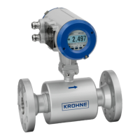
Handling, installation location, and mounting considerations for the ultrasonic flow sensor.
Proper grounding procedures to prevent electrical shock hazards and ensure safety.
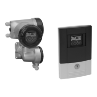
Instructions for electrically connecting the flow sensor to the flow converter using sensor cables.
Wiring the PT100 temperature sensor from the flow sensor to the I/O-rack module.
Connecting the flow converter to the I/O-rack using a shielded signal cable.
| Process Connection | Flanged |
|---|---|
| Communication | HART, Modbus |
| Power Supply | 24 V DC |
| Approval | ATEX, IECEx |
| Protection Class | IP 67 |
| Device Type | Flow Meter |
| Measurement Principle | Ultrasonic |
| Application | Liquid flow measurement |
| Measuring Range | 0.1 to 10 m/s |
| Temperature Range | -40...160 °C |
| Pressure Range | Up to 40 bar |
| Accuracy | ± 1% |
| Output Signals | 4…20 mA, pulse, frequency |
| Output Signal | 4-20 mA |
| Type | Ultrasonic Flow Meter |