EasyManua.ls Logo

KROHNE UFC 030 F EEx Series User Manual

KROHNE UFC 030 F EEx Series
33 pages
To Next Page IconTo Next Page
Page #1 background imageLoading...
Page #1 background image
GR
Electromagnetic flowmeters
Variable area flowmeters
Mass flowmeters
Ultrasonic flowmeters
Vortex flowmeters
Flow controllers
Level measuring instruments
Pressure and temperature
Heat metering
Communications technology
Switches, counters, displays and recorders
Engineering systems & solutions
DIN A4: 7.10028.31.00
©
KROHNE 06/20057.30942.32.00
Addition to the installation
and operating instructions
Universal 3-Beam
ultrasonic flowmeter
UFM 3030 K/EEx compact ultrasonic flowmeter
UFC 030 F/EEx ultrasonic flow converter
UFS 3000 F/EEx ultrasonic flow sensor
Subject to change without notice.

Other manuals for KROHNE UFC 030 F EEx Series

Question and Answer IconNeed help?

Do you have a question about the KROHNE UFC 030 F EEx Series and is the answer not in the manual?

KROHNE UFC 030 F EEx Series Specifications

General IconGeneral
SeriesUFC 030 F EEx
ApplicationFlow measurement in hazardous areas
Power Supply24 V DC
Protection ClassIP66/67
Hazardous Area ApprovalATEX, IECEx
TypeFlow Converter
Process ConnectionFlanged or threaded connections
Measurement RangeDepends on connected flow sensor
Accuracy±0.5% of reading
Operating Temperature-20°C to +60°C
Explosion ProtectionEEx ia IIC T6
Input SignalsSignals from connected flowmeter sensor
Output Signals4-20 mA, HART
CertificationATEX, IECEx
Housing MaterialAluminum or Stainless Steel (depending on version)
DisplayLCD

Summary

Universal 3-Beam Ultrasonic Flowmeter Introduction

Product Overview and Model Identification

Introduces the UFM 3030 series, its main components, and variations.

UFM 3030 K/i-EEx Compact Flowmeter

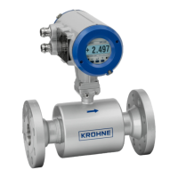
Details the compact version of the UFM 3030 ultrasonic flowmeter.

UFC 030 F/i-EEx Flow Converter

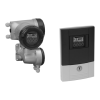
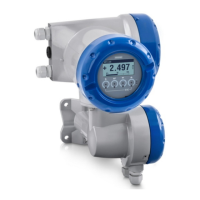
Describes the UFC 030 flow converter used with the flowmeters.

UFS 3000 F/i-EEx Flow Sensor

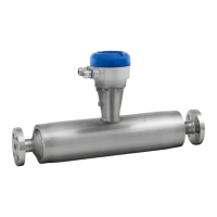
Explains the UFS 3000 flow sensor, the core measuring unit.

General Safety Advice and Precautions

Mandatory Installation and Operation Safety

Covers essential safety instructions for safe installation and operation of the device.

Understanding Safety Symbols

Explains the meaning and importance of safety symbols used in the manual and on the product.

Critical Safety for Hazardous Locations

Warning Against Unauthorized Device Modifications

Warns about the risks of modifying devices, impacting explosion safety.

Compliance with Hazardous Location Regulations

Emphasizes adherence to specific regulations for electrical installations in hazardous areas.

System Components and Approvals

Compact Flowmeter Design and Markings

Describes the design features and safety markings of the compact flowmeter.

Flow Sensor Details and Specifications

Flow Converter Unit Description

Flow Converter Electronics and Terminals

Electrical Data and Power Supply Specifications

Power Supply Unit Voltage Input Ranges

Lists the input voltage ranges for the power supply units (100-240V AC, 24V AC/DC).

Power Supply Unit Output Voltages and Currents

Details the output voltages and currents for electronics and analogue input drivers.

Electrical Interfaces and MODIS Module Data

Technical Data Summary

Electrical Connections and Safety

General Safety for Electrical Installations

Covers safety precautions for connecting the instrument to mains voltage.

Power Supply Connection Requirements

Details environmental requirements and connection procedures for the power supply.

Equipotential Bonding Procedure

Explains the requirements and procedure for equipotential bonding.

Standard Version Wiring and Terminals

Namur Version Wiring and Terminals

MODIS Version Wiring and Terminals

Flow Converter Operation and Cabling

Connection Diagrams for Flowmeter Systems

Sensor and Converter Connection Diagrams

Optional Sensor Connection Diagrams

High Temperature/Pressure Sensor Connections

Namur NE 43 Settings for Failure Indication

Configuring Current Output for Namur Failure

Explains how to set up current output functions according to Namur NE 43 for failure indication.

Service and Maintenance Procedures

Replacing Electronics Unit or Power Fuses

Details the procedure for replacing the electronics unit or power fuses.

Detailed Component Replacement Steps

Step-by-Step Electronics Unit Replacement

Provides detailed instructions for safely replacing the electronics unit.

Replacing Mains and Analogue Input Fuses

Explains the process for replacing mains and analogue input fuses.

Related product manuals