Do you have a question about the KROHNE UFC 300 and is the answer not in the manual?
Explains the purpose and content of these supplementary instructions.
Describes the Modbus RTU protocol and physical parameters as per EIA/TIA 485.
Provides interface, baud rate, protocol, coding, and distance specifications.
Details signal transmission, voltage, current, and resistance for the Modbus interface.
Details the terminals used for connecting the signal converter to Modbus.
Explains slave device connection, common signal line, and termination resistors.
Lists configurable parameters for Modbus RS485 connection including slave address and baud rate.
Defines the structure of Modbus RTU query and response frames, including silent periods and data fields.
Explains how bits and registers are transmitted, including 8, 16, and 32-bit value formats.
Describes the four types of data references and their associated Modbus register ranges and access rights.
Lists the Modbus function codes supported by the signal converter, with decimal and hexadecimal values.
Details the format and types of Modbus error messages returned by the signal converter.
Explains how to retrieve identification information like vendor name, product code, and revisions.
Describes diagnostic operations such as retrieving error logs and communication counts.
Provides basic device operation functions like restart, reset errors, and apply changes.
Details how to read device status indicators, such as unsaved changes pending.
Lists various measurement parameters like flow velocity, volume flow, and mass flow with units.
Describes how to read status signals according to the NAMUR NE 107 standard.
Lists auxiliary measurement parameters such as velocity of sound, gain, and signal quality.
Details totaliser controls for start/stop/reset and values for totaliser 1, 2, and 3.
Explains the procedure for performing zero calibration, recommended for trained service engineers.
Lists parameters related to process inputs, including flow direction and linearization.
Details parameters related to installation, such as pipe material, wall thickness, and fluid type.
Configures communication parameters like baud rate, transmission delay, parity, and stop bits.
Maps status groups to NAMUR NE 107 status signals for diagnostics and monitoring.
Describes the process for saving and restoring the device configuration settings.
Provides a detailed flowchart and steps for performing the zero calibration procedure.
Lists checks for troubleshooting when no response is received from the signal converter.
Identifies common causes of intermittent communication errors in Modbus connections.
Explains the 'Illegal Function' error and how to check valid Modbus functions.
Details four reasons for 'Illegal Data Address' errors related to register addresses and data types.
Explains 'Illegal Data Value' errors caused by writing values outside permitted register limits.
Maps Modbus input registers to NAMUR NE 107 status groups for signal interpretation.
Defines the meaning of status signals (F, C, S, M) used in the NAMUR NE 107 standard.
Provides a detailed breakdown of supported Modbus function codes and their request/response formats.
Explains the format for writing hexadecimal and decimal values.
Provides definitions for common Modbus and technical terms used in the document.
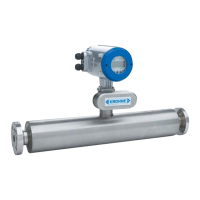
| Brand | KROHNE |
|---|---|
| Model | UFC 300 |
| Category | Measuring Instruments |
| Language | English |






 Loading...