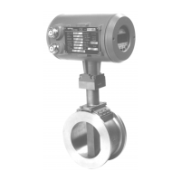
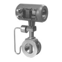
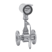
The VFC 200 is a signal converter for vortex flowmeters, designed to integrate with PROFIBUS PA networks. It supports PROFIBUS device with MBP Physical Interface and PA Profile 3.02 (2.0.2_/_190111).
Function Description
The VFC 200 signal converter translates the vortex flowmeter's signals into PROFIBUS PA communication. It acts as a slave device within the PROFIBUS network, allowing for the transmission of process values, diagnostic information, and configuration data to a master device (e.g., a PLC or engineering workstation). The device supports a range of function blocks, including Flow Transducer, Auxiliary Transducer, Analog Input, Totalizer, and Analog Output, which enable comprehensive measurement and control functionalities within the PROFIBUS PA environment.
The device's software includes a GSD file for integration into PROFIBUS DP communication networks, allowing for the configuration of parameters and functions. It supports both "Classic Status and Diagnosis" and "Condensed Status and Diagnosis" modes, providing flexibility in how diagnostic information is presented and managed. The VFC 200 also features an "Ident. Number Selector" for automatic adaptation to the network or manual selection of specific manufacturer and profile identifiers, ensuring compatibility and proper communication within diverse PROFIBUS setups.
Important Technical Specifications
Hardware:
- Type: PROFIBUS MBP interface according to IEC 61158-2 with [MBP = Manchester Coded Bus Powered]
- Connection: Independent of polarity at electrical connection
- Base current: 16 mA
- FDE (Fault Disconnection Electronics): Yes, separate fault disconnection electronics provided [FDE = Fault Disconnection Electronics]
- Fault current: 6 mA [Fault current = max. continuous current – base current]
- Starting current: Less than base current
- Ex approval: Ex ia IIC or Ex ia IIC/IIB, FISCO Device
Software:
- GSD: GSD file on CD-ROM or from internet site
- Supported GSD: KR014541.GSD, PA139741.GSD
- Device profile: PROFIBUS PA Profile 3.02; conformance class B, compact
- Address range: 0...126 (default 126)
- 0...125 via PROFIBUS service set_slave_add
- 0...126 via local display
- 126 via factory_reset = 2712
- Local control: Local display and operator interface at device
- SAPs (Service Access Points): 2 x MS1 SAPs – acyclic interface to PLC
- 3 x MS2 SAPs – the number of MS2 Service Access Points is typically equal to the maximum number of master class 2 tools
- Function blocks:
- 1 x TB-Flow = Transducer Block Flow
- 1 x TB-Auxiliary = Transducer Block Auxiliary [– manufacturer specific / in connection with Analog Output Function Block]
- 1 x PB = Physical Block
- 5 x AI = Analog Input Blocks
- 2 x TOT = Totalizer Function Blocks
- 1 x AO = Analog Output Block
Function Block Types (Manufacturer specific Ident. Number [4541 hex]):
- Volume Flow (AI-FB): m³/h
- Vortex Freq. (AI-FB): Hz
- Volume (Totaliser-FB): m³
- Mass (Totaliser-FB): kg
- Density (AI-FB): kg/m³
- Temperature 1 (AI-FB): K
- Pressure (AI-FB): Bar
- Ext. Temp. (AO-FB): K
Function Block Types (Profile specific Ident. Number [9741 hex]):
- Volume Flow (AI-FB): m³/h
- Vortex Freq. (AI-FB): Hz
- Volume (Totaliser-FB): m³
Cyclic Data Transfer:
- Float value format: IEEE Standard 754 Short Real Number (4-byte float value)
- Status value: 1-byte status value
Usage Features
The VFC 200 offers flexible configuration options through its local display and operator interface, as well as via PROFIBUS communication. Users can adjust parameters related to flow measurement, totalization, and diagnostic settings. The device supports various measurement units for volume flow, mass, density, temperature, and pressure.
Commissioning and Operation:
- Parameter Download: Parameters can be downloaded via PROFIBUS or manually changed via the local display.
- Factory Reset: A factory reset can be performed via PROFIBUS or the local display.
- Service Password: A service password is required to deactivate the "Service Parameter Lock" and make parameter changes.
- Cyclic Data Transfer: The device supports automatic and engineering tool-based configuration of cyclic data transfer, allowing for the selection of function blocks and their mapping to specific slots for continuous data exchange with the master.
- Status and Diagnosis: The VFC 200 provides detailed diagnostic information, including device-internal self-tests, hardware failures, measurement failures, configuration invalidity, restarts, cold starts, and maintenance requirements. These diagnostics are categorized into "Condensed Status and Diagnosis" and "Classic Status and Diagnosis" modes, with various event groups (e.g., Process, Electronics, Sensor, Configuration) to pinpoint issues.
- Event Filtering: Users can filter "Single events" and "Event groups" to focus on relevant diagnostic messages, improving troubleshooting efficiency.
- Display Settings: The local display allows for viewing of various measurements (e.g., volume flow, mass flow, gross power, net power, FAD, temperature, pressure, density, vortex frequency, velocity, specific enthalpy, specific heat capacity, Reynolds number) and message history.
PROFIBUS Settings:
- Quick Setup: Provides quick access to identification number, station address, cluster settings, and totalizer units.
- Menu "B Test": Displays current values for analog inputs and totalizers.
- Menu "C Setup": Allows configuration of PROFIBUS PA settings, physical block, tag, identification number, station address, transducer block flow, and various measurement parameters (e.g., volume flow unit, nominal size, time constant, error behavior, replacement value).
- Menu "D Service": Includes parameters for PROFIBUS cold start and identification number.
Maintenance Features
The VFC 200 incorporates several features to aid in maintenance and ensure reliable operation:
- Diagnostic Information: Comprehensive diagnostic messages, including those related to maintenance alarms and demands, help identify potential issues before they lead to critical failures.
- Status Monitoring: The device's status values (e.g., "bad," "uncertain," "good") provide immediate feedback on the quality and reliability of measurements.
- Error Behavior Configuration: Users can define how the device behaves in case of errors, including setting replacement values for measurements, which can be crucial for maintaining process control during transient faults.
- Firmware Updates: The device's software can be updated, allowing for improvements and bug fixes, which contributes to long-term maintainability.
- Ident. Number Selector: The ability to select specific manufacturer and profile identifiers ensures compatibility with various PROFIBUS master systems, simplifying integration and reducing potential maintenance issues related to communication.
- Event Logging: The device's message history view allows for the review of past events and diagnostic messages, aiding in root cause analysis and proactive maintenance planning.
- PROFIBUS Cold Start: A PROFIBUS cold start can be initiated to reset all parameter values to their default settings or to the values stored in the PROFIBUS master system, which can be useful for troubleshooting or re-commissioning.