PROFIBUS PA
2
5
VFC 200
www.krohne.com06/2019 - 4005059401 - AD VFC200 PB-PA R01 en
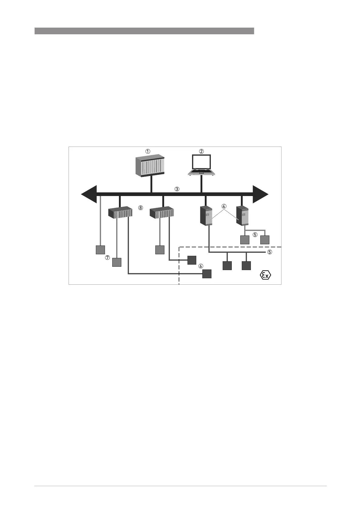
2.2 System configuration of PROFIBUS PA network
The following diagram shows a typical instrumentation with PROFIBUS PA devices with MBP
interface in hazardous and non-hazardous locations, including connections of conventional
devices (e.g. with 4...20 mA signals) in a PROFIBUS network.
As a rule, the PROFIBUS PA segment is connected to a segment coupler which, among other
things, carries out the conversion to the PROFIBUS DP bus line. It should be mentioned that the
segment coupler is normally set to a fixed baud rate on the DP side.
Figure 2-1: PROFIBUS PA network
1 Control system (PLC); class 1 master
2 Engineering or operation control tool; class 2 master
3 PROFIBUS DP network with max. 12 Mbit/s
4 PROFIBUS PA segment coupler DP / PA
5 PROFIBUS PA network with 31.25 kbit/s
6 HART
®
device
7 More devices with 4…20 mA
8 Analogue I/O module
 Loading...