GB-2
Checking the usage
Intended use
Actuator IC 40
It is designed for all applications that require precise,
controlled rotary movement between 0° and 90°.
The combination of actuator IC40 and control ele-
ment is designed to adjust volumes of gas and air
on various appliances and flue gas lines. IC40 is
adjusted and commissioned using the BCSoft V4.x
programming software.
This function is only guaranteed when used within the
specified limits– see page9 (Technical data). Any
other use is considered as non-compliant.
Type code
Code Description
IC 40 Actuator
S Emergency closing function
A Mains voltage: 100 – 230 V AC, 50/60 Hz
Torque:
2.5 Nm
3 Nm
A
D
4 – 20 mA analogue input
Digital input
R10
1)
1 kΩ feedback potentiometer
1)
Optional
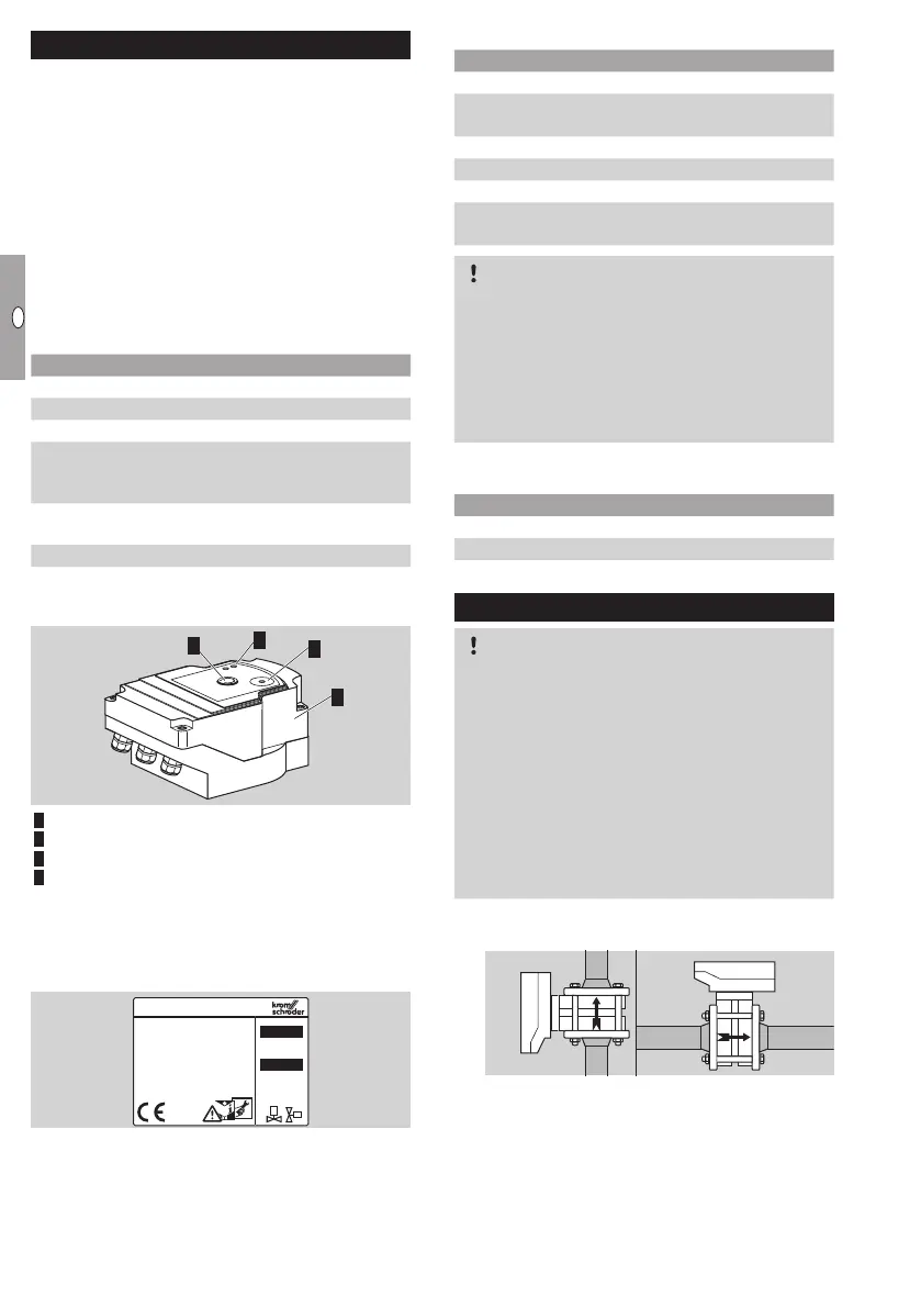
Part designations
2
3
1
4
1 Housing cover
Position indicator
Red and blue LEDs
4 Optical interface
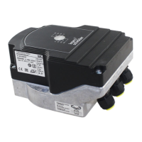
Type label
Mains voltage, electrical power rating, enclosure,
ambient temperature, torque and installation posi-
tion– see type label.
D-49018 Osnabrück, Germany
www.kromschroeder.com
IC
P:
U:
Combination of actuator with butterfly valve
Type IC 40 + butterfly valve BV..
IBG IC 40 + BVG (for gas)
IBGF IC 40 + BVGF (for gas, clearance-free
valve)
IBA IC 40 + BVA (for air)
IBAF IC 40 + BVAF (for air, clearance-free valve)
IBH IC 40 + BVH (for hot air and flue gas)
IBHS IC 40S + BVHS (for hot air and flue gas,
with emergency closing function)
CAUTION
The emergency closing function should be used
only for the intended function. If the emergency
closing function is used for controlled shut-down
or for intermittent switching of the burner, this will
reduce the service life of the butterfly valve and
actuator. Such applications do not correspond to
the intended use.
Combination of actuator with linear flow
control
Type IC 40 + linear flow control
IFC 1 IC 40 + linear flow control VFC, size1
IFC IC 40 + linear flow control VFC, size3
Installation
CAUTION
Please observe the following to ensure that the
actuator is not damaged:
– Do not store or install the unit in the open air.
– The device must not be installed in a public
place. It must be accessible to authorized
personnel only. Unauthorized personnel could
make changes which could cause the system
to become unsafe or dangerous.
– Dropping the device can cause permanent dam-
age. In this event, replace the entire device and
associated modules before use.
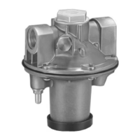
▷ Installation in the vertical or horizontal position,
not upside down.
▷
For the assembly of actuator and butterfly
valve, and for installation in the pipework, see
www.docuthek.com → Elster Thermal Solutions→
Products→ 03Valves and butterfly valves→
Butterfly valves BV.. operating instructions or
Linear flow controls IFC, VFC operating instruc-
tions.
▷
Do not insulate the actuator with thermal insu-
lation.