GB-9
Technical data
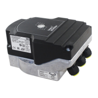
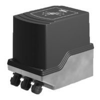
Purpose of control: operating control, electric
actuator.
Mains voltage: 100–230VAC, ±10%, 50/60Hz,
the actuator automatically adjusts to the respec-
tive mains voltage.
Power consumption: 10.5 W/21 VA at 230 V AC,
9 W/16.5 VA at 120 V AC.
Switch-on peak current: max. 10 A for max. 5 ms.
Screw terminals using the elevator principles for
cables up to 4 mm
2
(single core cables) and for
cables up to 2.5 mm
2
with wire end ferrules.
Angle of rotation: 0 – 90°, setting accuracy
<0.05°.
Holding torque = torque as long as mains voltage
is applied.
Independently mounted control.
Pollution degree: 3 (outside of enclosure)/2 (within
enclosure).
Rated impulse voltage: 4000 V.
Impedance protected motor.
2 digital inputs:
24 V DC or 100 – 230 V AC each.
Current requirement of digital inputs:
24 V DC: approx. 5 mA eff,
230 V AC: approx. 3 mA eff.
1 analogue input (optional):
4 – 20 mA (load impedance switchable from 50Ω
to 250Ω).
Potentiometer (optional): 1 kΩ ± 20%,
linearity tolerance: ± 2%, max. capacity: 0.25W,
conductive plastic element.
Tap wiper at high resistance, see page4
(Feedback).
2 digital outputs:
Signalling contacts designed as relay change-
over contacts. Contact current of digital outputs:
min.5mA (resistive) and max. 2A (resistive).
Enclosure:
IC 40: IP 64, in conjunction with BVH: IP 65,
IC 40: Nema 2, in conjunction with BVG, BVA or
BVH: Nema 3.
Safety class: I.
Duty cycle: 100%.
Type of action to EN 60730: type 1C.
Software class A.
Overvoltage category III.
Electrical connection:
Line entrance: 3 x M20 plastic cable glands.
Ambient temperature:
-20 to +60°C, no condensation permitted.
Storage temperature: -20 to +40°C.
Max. installation altitude: 2000 m AMSL.
Type
Running time [s/90°] Torque [Nm]
50 Hz/60 Hz 50 Hz 60 Hz
IC 40 4.5 – 76.5 2.5 2.5
IC40S 4.5 – 76.5 3 3
On the IC40, the running time and torque are
independent of the mains frequency. The running
time can be freely programmed between the limits
of 4.5 and 76.5s.
Specifications on the typical designed lifetime:
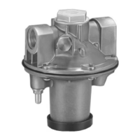
The following specifications on the designed
lifetime of the actuator relate to typical applications
with butterfly valves BVA, BVH and VCG.
Mechanical switching cycles (0° – 90° – 0°/0% –
100% – 0%):
IC 40 with VFC: 5 million cycles
IC 40 with BVA/BVG: 5 million cycles
IC 40 with BVAF/BVGF: 5 million cycles
IC 40 with BVH/BVHx: 3 million cycles
Typical number of operating cycles of the digital
outputs RO1 and RO2:
Switching current Switching cycles
5 mA 4,000,000
2 A 250,000
Logistics
Transport
Protect the unit from external forces (blows, shocks,
vibration). On receipt of the product, check that the
delivery is complete, see page2 (Part designa-
tions). Report any transport damage immediately.
Storage
Store the product in a dry and clean place.
Storage temperature: see page9 (Technical data).
Packaging
The packaging material is to be disposed of in ac-
cordance with local regulations.
Disposal
Components are to be disposed of separately in
accordance with local regulations.