GB-4
Feedback
▷
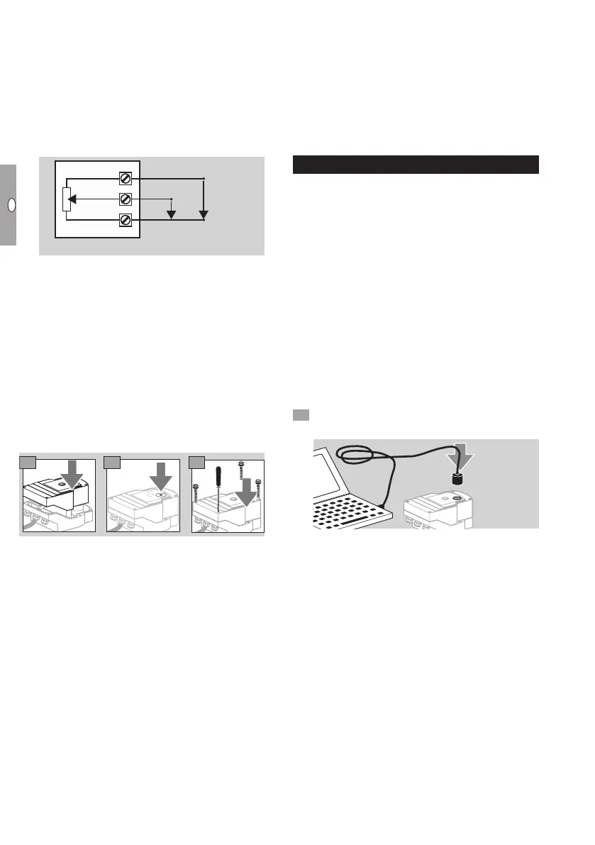
A feedback potentiometer offers the option of
monitoring the current position of the actuator.
▷
The potentiometer is an optional feature. It is
installed at the factory and cannot be retrofitted.
▷ The potentiometer must be utilized as a voltage
divider. The change in position of the potentiom-
eter wiper (which corresponds to the actuator
position) can be measured as a changing voltage
between U
-
andU
M
.
U+
U
M
U-
22
21
20
Potentiometer
Wiper
(e.g. 1 V DC)
(ground)
▷
Other circuit layouts produce measurement
results that are inaccurate and do not remain
stable over a long period of time or are non-
reproducible. They also reduce the service life
of the feedback potentiometer.
▷ The available range (resolution) depends on the
parameterization of the setting range.
▷
The potentiometer is only suitable for connection
of SELV and PELV.
▷ Max. power = 0.25W, max. voltage= 15V.
▷
Follow the reverse procedure when reassembling.
▷
Carefully align the optical waveguides on the
circuit board with the marking on the housing
cover (circle).
9 10
11
▷ Re-tighten the cover screws in order to ensure
that the housing cover is grounded.
▷
A PC or notebook, the BCSoft V4.x program-
ming software and an opto-adapter PCO200 or
PCO300 are required for further commissioning,
see page5 (Accessories).
▷ The opto-adapter establishes a connection be-
tween the PC and the actuator.
BCSoft
▷ The current software and operating instructions
can be downloaded from www.docuthek.com,
see page5 (Accessories). To do so, registra-
tion in the DOCUTHEK is required.
▷
BCSoft V4.x allows you to select the type of con-
trol, the operating mode, running times, opening
angles and intermediate positions.
▷
Various operating modes, which may be modified,
are stored in the actuator.
▷
The actuator can also be controlled “by hand”
using BCSoft.
▷
Service technicians can call up statistical data
using BCSoft.
▷
Once set, all the parameters can be saved on the
PC and copied from there into other actuators.
▷
For detailed information on control, Manual
mode and statistics, see www.docuthek.com →
Elster Thermal Solutions → Products →
03Valves and butterfly valves → Actuators IC...
→ Technical Information IC40.
Establishing a connection to a PC
▷ Up-to-date antivirus software must be installed
on the PC used for parameterization.
There are two ways of establishing a connection to
a PC:
▷ Opto-adapter PCO 00: cable connection via
USB interface.
▷ Opto-adapter PCO 00: wireless connection
using Bluetooth.
▷
Follow the instructions provided in the enclosed
operating instructions of the corresponding opto-
adapter for installation of the driver and connec-
tion establishment.
▷ Operating instructions PCO 200 and PCO 300
(D,GB), see www.docuthek.com→ Elster Ther-
mal Solutions→ Products→ 03Valves and but-
terfly valves→ Actuators IC20, IC40, IC50→
PCO...
• Place the sensor in the centre of the marking
(circle) provided for this purpose.
▷ The film on the marking must be clean and un-
damaged.
▷
When connecting to BCSoft, a connection to
the IC 40 is established from the PC/notebook.
▷
If a connection fails to be established, the proce-
dure can be repeated by pressing function key F3.
▷ The opto-adapter is to be removed again follow-
ing successful parameterization.