GB-3
Wiring
WARNING
Electric shocks can be fatal!
– Before working on electrically live components,
ensure they are disconnected from the power
supply.
– It must be possible to isolate the actuator from
the power supply. Provide a double pole switch.
▷ Install supply and signal lines separately.
▷
Conductors which have not been connected
(spare conductors) must be insulated at their
ends.
▷ Cables should be installed well away from high-
voltage lines of other devices.
▷ Observe EMC Directive for installation of signal
lines.
▷
If the power supply is susceptible to frequent
voltage peaks, we recommend that an electric
filter be used.
▷
Use temperature-resistant supply cables (≥ 90°C
and min. 1 – 1.5 mm² or AWG 14 – 18).
▷ Use cables with wire end ferrules.
▷ Cable cross-section: max. 2.5mm².
▷
For information on assignment of the inputs
and outputs, see www.docuthek.com → Elster
Thermal Solutions→ Products→ 03Valves and
butterfly valves→ Actuators IC... → Technical
Information IC40.
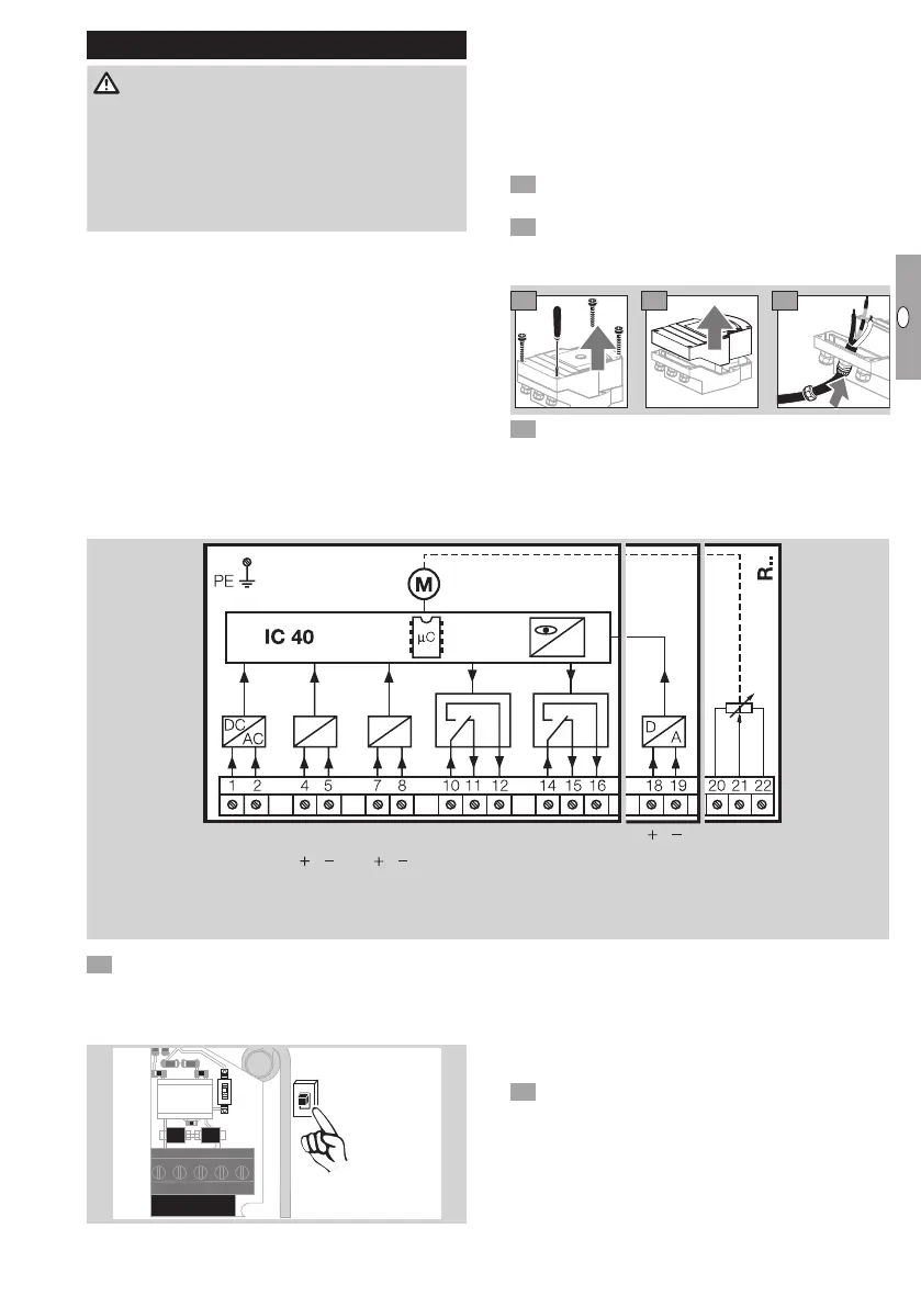
1 Disconnect the system from the electrical power
supply.
Shut off the gas supply.
▷
Before opening the unit, the fitter should ground
himself.
3 4
5
6 Wire as shown on the connection diagram.
▷ Do not connect power supply and digital inputs
to different phases of a three-phase current sys-
tem.
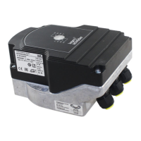
Connection diagram
N L1 L1 N L1 N
100–230 V AC
50/60 Hz
COM NC NO COM NC NO
100–230 V AC
24 V DC
max. 230 V AC
max. 2 A
Power DI 1 DI 2 RO 1 RO 2 IN Analog
4–20 mA
Potentiometer
max. 0,25 W
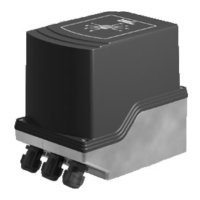
7 Assign inputs according to application.
▷ The load impedance of the 4 – 20 mA input can
be modified using the switch on the main circuit
board.
ON
1 50 Ω
ON
1
250 Ω
50 Ω
250 Ω
▷ Digital input DI 1/DI 2: in the case of 24VDC,
check the polarity.
▷
Analogue input IN Analog: 4 – 20 mA, check
the polarity.
▷
For further information on the inputs, see
page9 (Technical data).
8 Assign outputs according to application.
▷ Digital outputs RO 1 and RO 2: signalling con-
tacts designed as relay change-over contacts.
▷ For further information on the outputs, contact
current and relay contacts, see page9 (Tech-
nical data).