VI - 9
Settings
6.7 Setting the clutch
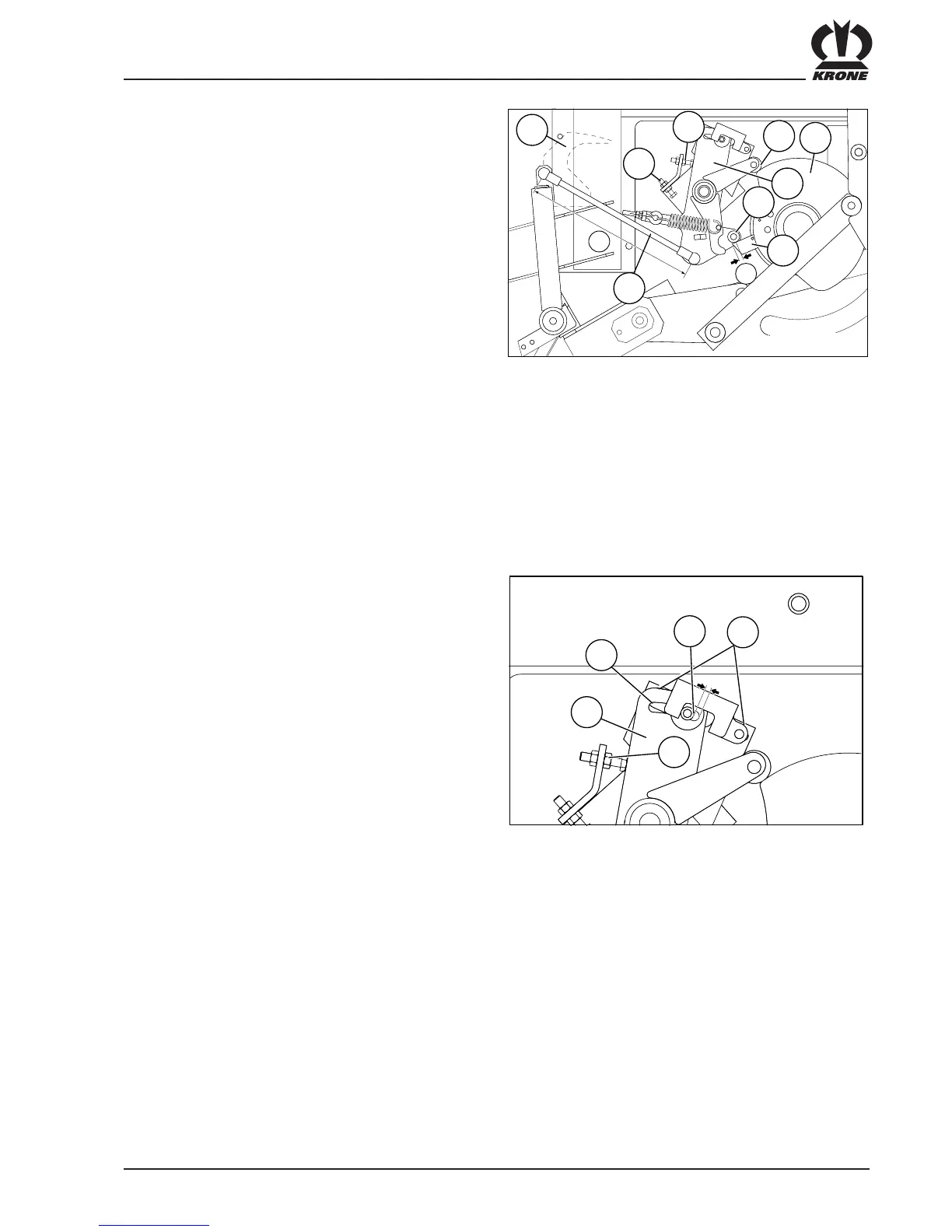
1. Adjust the adjusting screw (14) so that the clutch
switch ratchet (18) sits B = 8 – 10 mm on the
middle of the roller (19) when the clutch is switched
off.
2. If the anvil (15) sits on the adjusting screw (14), the
rear of the back holder rake (12) has to stand
parallel to the back wall of the feed packer channel.
You can set it at the threaded rod (13) (arrange
measure of A = 438 mm).
3. After rotation the roller (16) will drop down the
outside margin of the pulley (17). When the back
holder rake pulls back the anvil will apply to the
adjusting screw. In this position the top of the back
holder rake (12) still has to reach 5 - 10 mm into the
feed packer channel. You can set it with the
adjusting screw (11).
6.8.2 Setting the damper equipment
The damper equipment prevents the anvil from switching
on the VFS-clutch through its own movements. The
adjustable tension of the pressure spring (20) depends
on e.g. the condition of the brake (wear grade, paint,
rust).
To check the spring's tension you have to actuate the
back holder rake (12). For that reason put some feeder
in the big baler. If the back holder rake swings back again
(at full number of revolution), the anvil (15) is allowed to
bounce back from the adjust screw (14) max. 1 - 3 mm.
If the anvil bounces back further you will have to increase
the tension of the pressure spring (20).
If the back holder rake swings out, the anvil has to arrive
at the adjust screw (11). If not, reduce the spring tension.
6.8.1 Lateral setting of the damper
equipment
To compensate tolerances because of welding and
adaptation the damper equipment is adjustable.
Checking the settings:
Press the anvil (15) against the adjust screw (14). In this
position there should be a gap of 6 - 8 mm to the front
from the strech screw for the pressure spring (20) in the
slot (22) of the anvil. To correct the adjustment undo the
screws (21) and correspondingly displace the damper
equipment.
6.8 Damper equipment
A
B
12
11
14
15
16
18
19
17
13
BP-VFS-091






 To Next Page