Caution
Caution
!
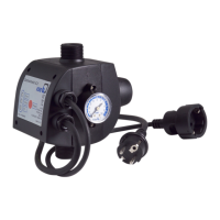
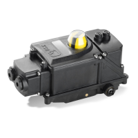
Controlmatic E.2
21
2.6 Unauthorized modification and manufacture of
spare parts
Modifications or alterations of the equipment supplied are
only permitted after consultation with the manufacturer.
Original spare parts and accessories authorized by the manu-
facturer ensure safety.
The use of other parts can invalidate any liability of the manu-
facturer for resulting damage.
2.7 Unauthorized modes of operation
The warranty relating to the operating reliability and safety of
the device s upplied is only valid if the device is used in accord-
ance with its designated use as described in section 4 of this
manual. The limits stated in the operating instructions must not
be exceeded under any circumstances.
3 Transport and temporary storage
3.1 Transport
To prevent damage during transport, the
automatic control unit must not be handled
or lifted by the power cable, and it must be protected against
any impacts or falls.
3.2 Temporary storage/Preservation
The device should be stored in a dry, dark, frost-proof room not
exposed to sunlight.
4 Description of the product and
accessories
4.1 Technical specification
The Controlmatic E.2 control unit is designed for controlling au-
tomatic pump starting and stopping.
The pump is started after a consumer installation has been
opened, as indicated by a flow and resulting pressure drop in
the piping system.
Controlmatic E.2 detects a fluid flowin the piping system.When
flow has stopped, the unitwillstop thepump afterapprox.5sec-
onds.
Apart from the automatic switchgear, the unit also comprises a
built-in membrane designed to provide a water reserve and
thus limit the switching frequency of the unit.
A swing check valve prevents the built-up pressure in the dis-
charge line from decreasing again.
Consumer installation closes
(zero flow)
Pump operating range
Consumer installation opens
(start-up pressure)
Factory setting: 1.5 bar
Pp ≥ 2.2 bar (Pc+0.7 bar)
Pp = Pump pressure
Pc = Pressure setting of Controlmatic E.2 (1.5 bar)
Please note:
Controlmatic E.2 cannot be used for pressure boosting. Its
outlet pressure equals the pump’s discharge pressure.
Fluids handled:
D Clean water without solid particles
D Chlorinated swimming-pool water (max. 0.3 %)
D Water-soluble s ubstances
D Fertilizers
D Wood preservatives and pesticides
(Unit must be flushed through after every application).
The unit must not be used for the following fluids:
D corrosive fluids
D flammable fluids
D explosive fluids
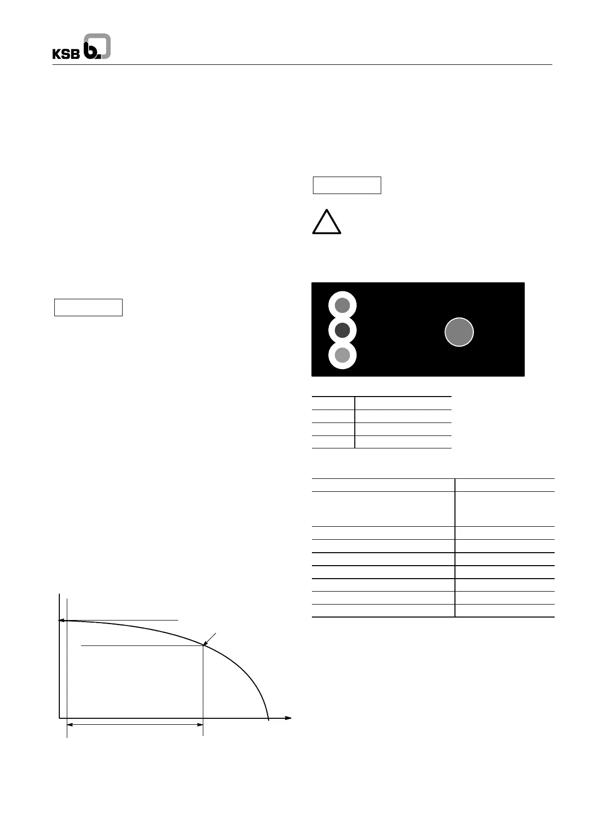
4.2 Indicator lamps
Reset
Power
On
Failure
Key:
Green
Power (Energized)
Red Failure (Fault)
Amber: On (Running)
Reset Initialization
4.3 Technical data
Max. operating pressure
10 bar
Max. amperage
(Check against pump operating
manual)
10 A
Pumped fluid temperature 0--60C
Max. flow rate 10 m
3
/h
Min. flow rate 0.09 m
3
/h
Voltage/Frequency 220--240 V, 50/60 Hz
Enclosure IP 65
Power supply cable 1.5 m
Minimum start-up pressure 1.5 bar
4.4 Designation
Type: Controlmatic E.2.
Ident. No.: 39 300 031
4.5 Design details
Controlmatic E.2 is made of high-grade plastic materials only.
KSB’s scope of supply includes:
D Power cable and standardized plug
D Standardized plug s ocket
D Integrated swing check valve
4.6 Accessories
D The automatic control unit is supplied ready to be plugged in.
Accessories can be ordered through your distributor.
 Loading...