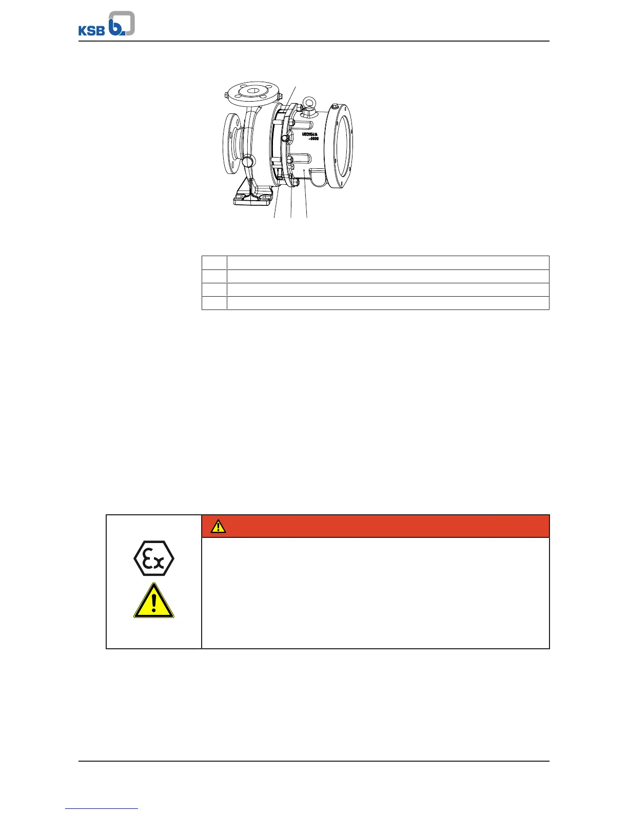
Fig.24: Fastening the bearing bracket lantern to the casing cover (design with
clamped casing cover)
1 Casing cover 161
2 Hexagon head bolt 901.31
3 Bearing bracket lantern 344
4 Marking on casing cover facing upwards
3. Place bearing bracket lantern 344 onto casing cover 161 (see illustration:
Fastening the bearing bracket lantern to the casing cover (design with clamped
casing cover)).
4. Mount bearing bracket lantern 344 on casing cover 161 with hexagon head bolts
901.31. Observe the tightening torques. (ðSection7.6,Page86)
5. Remove the guard.
6. Fit studs 902.04.
7.5.6 Fitting the rolling element bearings
ü The notes and steps stated in (ðSection7.5.1,Page70) to
(ðSection7.5.5,Page76) have been observed/carried out.
ü The individual parts have been placed in a clean and level assembly area.
ü All dismantled parts have been cleaned and checked for wear.
ü Any damaged or worn parts have been replaced by original spare parts.
ü The sealing surfaces have been cleaned.
DANGER
Excessive temperatures caused by increased friction at the joint rings
Explosion hazard!
Fire hazard!
Damage to the pump set!
Risk of burns!
▷ Never apply paint to joint rings 411.77 and 411.78.
▷ Ensure that the joint rings have contact in the axial direction and are slightly
pre-loaded.
1. Insert circlip 932.02 into the groove of the bearing's outer ring (rolling element
bearing 321.02).
2. Press rolling element bearing 321.02 onto shaft 210.01 until it rests against the
shaft shoulder (do not heat up the rolling element bearing) and secure it with
circlip 932.80. Circlip 932.02 is fitted on the side pointing towards the drive end.
On oil-lubricated models, the shield of rolling element bearing 321.01 is fitted on
the side pointing towards the pump end.
 Loading...