2 SETUP 4
M01064-10
– Connect the plug-in connector for the FI warning lamp. Position FI warning lamp
in the holder.
–
Wind the cable for the service hour counter
(optional) around the ignition
wire as described in the instructions enclosed, and secure using a cable tie.
– Mount the service hour counter (optional) on the holder.
– Position the holder for the FI warning lamp and holder for the service hour
counter (optional).
–
Mount and tighten screws
.
Guideline
Remaining screws, chassis M6 10 Nm
(7.4 lbf ft)
–
Mount cable holder
to the frame.
S00867-12
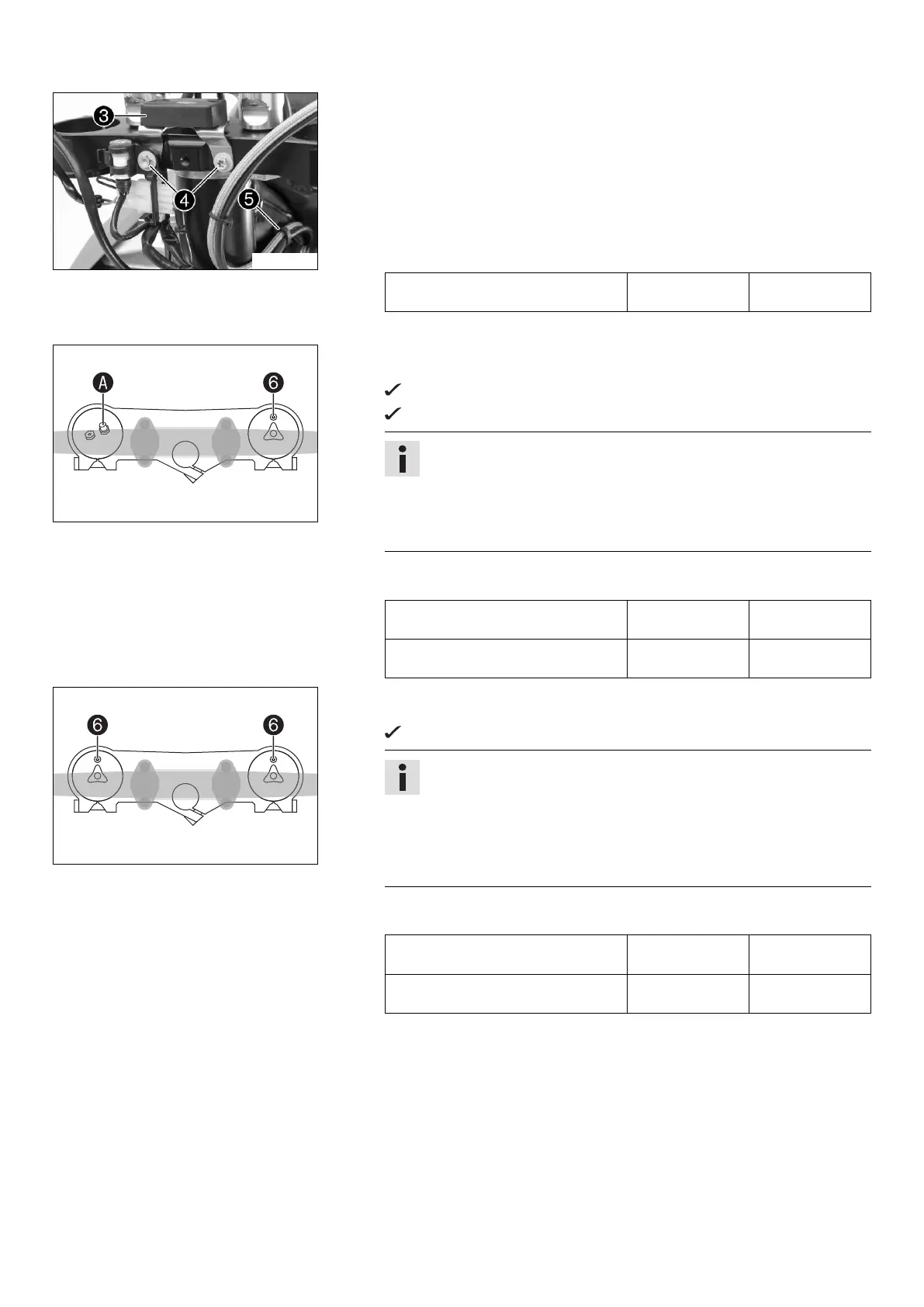
(SX‑F EU)
– Position the fork legs.
Bleeder screw
of the right fork leg is positioned to the front.
Left fork leg valve
is offset by approx. 20° to the front.
Info
Grooves are milled into the side of the upper end of the fork legs. The
second milled groove (from the top) must be flush with the top edge of
the upper triple clamp.
The air suspension is located in the left fork leg. The pressure and
rebound damping is located in the right fork leg.
– Tighten the screws of the triple clamp.
Guideline
Screw, top triple clamp M8 17 Nm
(12.5 lbf ft)
Screw, bottom triple clamp M8 12 Nm
(8.9 lbf ft)
402556-13
(SX‑F US, XC‑F US)
– Position the fork legs.
Bleeder screws
are positioned toward the front.
Info
The rebound damping is located in the right fork leg (red adjusting
screw). The compression damping is located in the left fork leg (white
adjusting screw).
Grooves are milled into the side of the upper end of the fork legs. The
second milled groove (from the top) must be flush with the top edge of
the upper triple clamp.
– Tighten the screws of the triple clamp.
Guideline
Screw, top triple clamp M8 17 Nm
(12.5 lbf ft)
Screw, bottom triple clamp M8 12 Nm
(8.9 lbf ft)

 Loading...