G-24
SM-E2B SERIES, WSM
G GENERAL
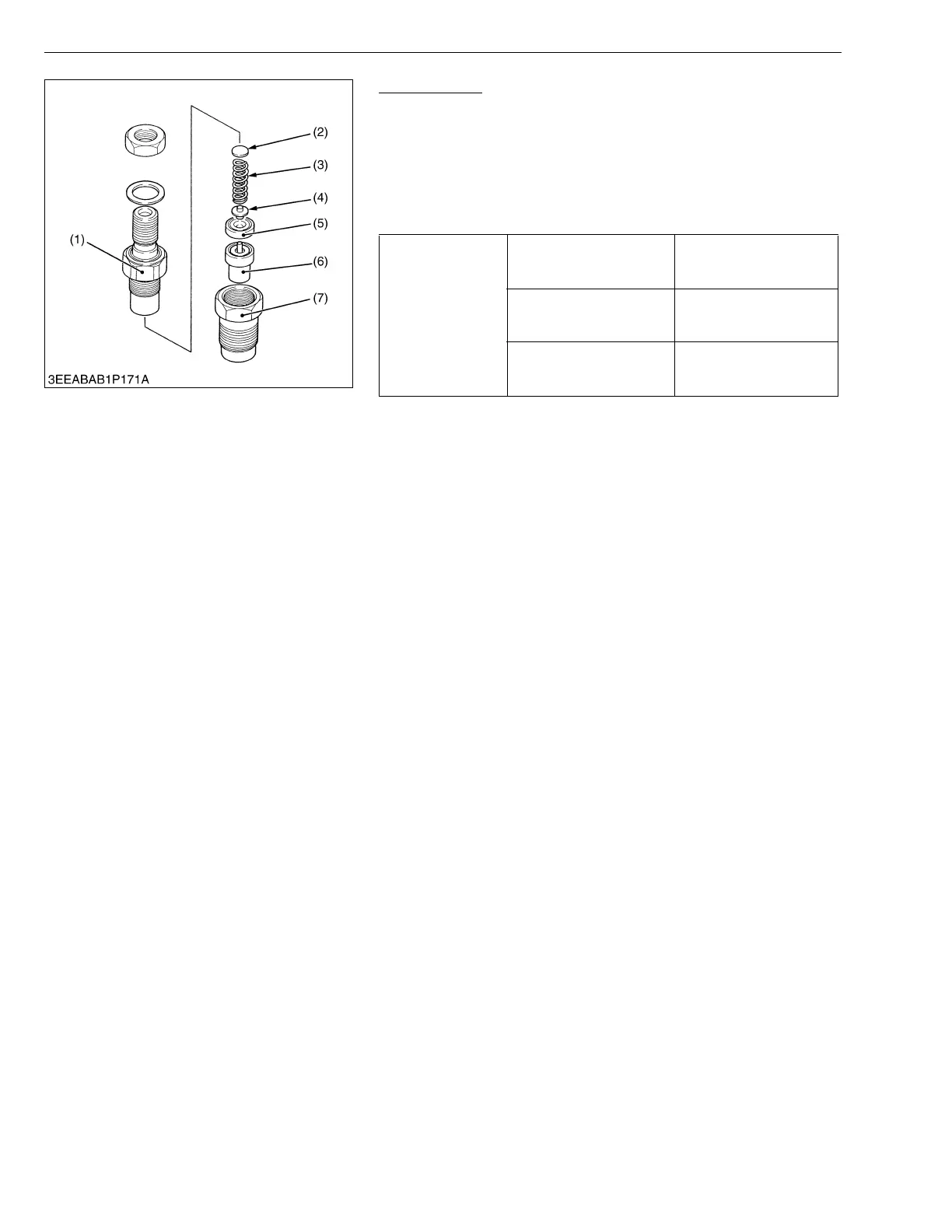
Nozzle Holder
1. Secure the nozzle retaining nut (7) with a vise.
2. Remove the nozzle holder (1), and take out parts inside.
(When reassembling)
• Assemble the nozzle in clean fuel oil.
• Install the push rod (4), noting its direction.
• After assembling the nozzle, be sure to adjust the fuel injection
pressure.
W1018491
Tightening torque
Nozzle holder
34.3 to 39.2 N·m
3.5 to 4.0 kgf·m
25.3 to 28.9 ft-lbs
Overflow pipe retaining nut
19.6 to 24.5 N·m
2.0 to 2.5 kgf·m
14.5 to 18.1 ft-lbs
Nozzle holder assembly
49.0 to 68.6 N·m
5.0 to 7.0 kgf·m
36.2 to 50.6 ft-lbs
(1) Nozzle Holder
(2) Adjusting Washer
(3) Nozzle Spring
(4) Push Rod
(5) Distance Piece
(6) Nozzle Piece
(7) Nozzle Retaining Nut